

 English
 Français
 Español
 Português
 عربى
عربى















 Knowledge
Why Rack Unit Height Still Matters in Modern Data Centre Planning
The rack unit (U) has been the fundamental unit of data centre space allocation for decades, yet its practical implications for infrastructure planning are frequently underestimated during the early stages of a facility design. A single rack unit represents 44.45 mm of vertical mounting space, and the difference between a 42U server rack and a 48U equivalent in the same footprint is 268 mm of additional usable height — enough to accommodate six additional 1U servers, two additional patch panels, or an additional power distribution unit without any change to floor area.
This vertical efficiency gain compounds across a facility. A row of twenty 48U cabinets provides the equivalent of 120 additional rack units compared to the same row populated with 42U cabinets — the equivalent of three fully populated 40U racks of additional capacity from the same floor space and power infrastructure investment. For facilities where floor area is constrained or expensive, the choice of rack height is a meaningful density lever that costs nothing in additional footprint.
The practical ceiling on rack height is set by two variables: room clear height, which must accommodate the cabinet plus cable management above, and the ergonomic limit for equipment servicing, since equipment mounted above approximately 2.1 m requires a step platform for safe access. Both constraints are known at the design stage and should be evaluated before rack height is standardised across a deployment.
Structural Load Ratings, Floor Loading, and the Engineering Reality Behind Cabinet Weight
A fully populated 45U server rack carrying dense storage arrays, high-memory compute nodes, and a top-of-rack switch can weigh 900–1,200 kg in operational configuration. This is before accounting for the weight of the cabinet enclosure itself, cable management hardware, and PDU assemblies. Floor loading at this weight, concentrated on the four levelling feet of a standard cabinet, produces point loads that exceed the structural capacity of many commercial building floor slabs without load-spreading provisions.
Wanma Technology's background in supplying communication cabinet infrastructure for national high-speed railway and urban rail transit environments — settings where structural compliance and long-term load-bearing reliability are non-negotiable — reflects the same engineering rigour that applies to data centre cabinet structural specifications. The relevant parameters for floor loading assessment include:
- Maximum IT equipment weight at full population, not average or partial-load weight
- Cabinet frame rated load capacity, which should exceed the maximum population weight with a minimum 20% safety margin
- Foot contact area and whether load-spreading base plates or rails are required to distribute weight across a larger floor contact zone
- Dynamic load considerations for seismic zones, where lateral bracing and anchor point specifications must be validated against local seismic design standards
Facilities located in seismic zones should specify cabinets with four-point floor anchoring provisions and validated seismic ratings — typically expressed as compliance with GR-63-CORE NEBS Zone 4 or equivalent regional standards — rather than relying on cabinet weight alone for stability under lateral loading.
Cable Management Strategies That Scale With Rack Population
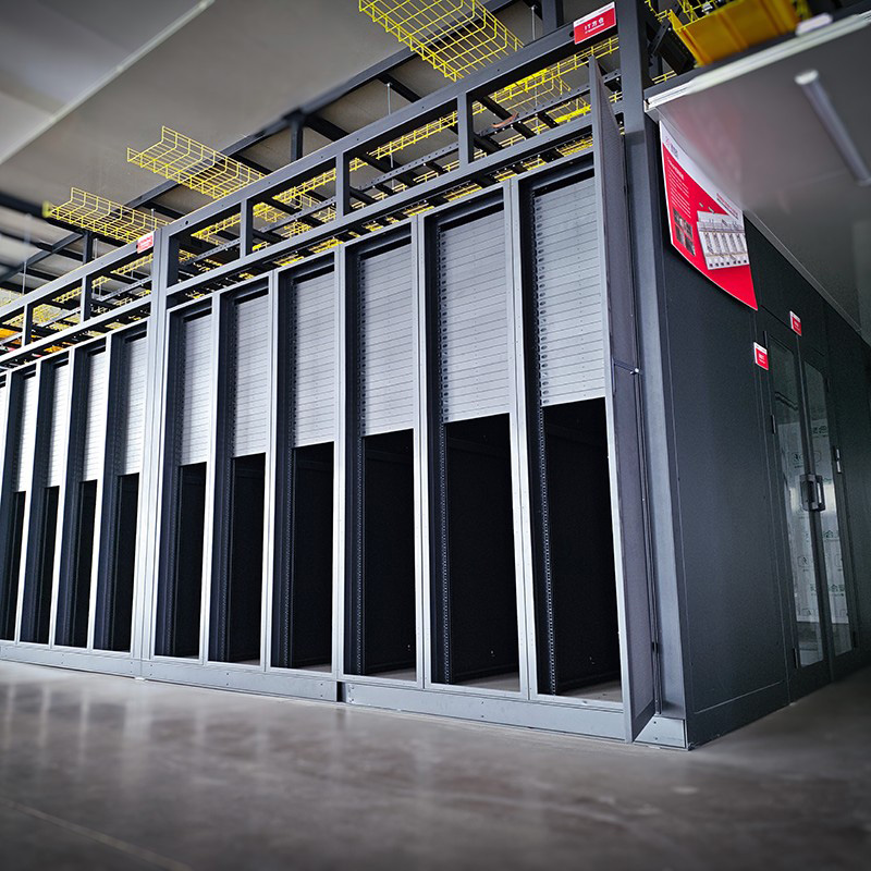
A rack type data center installation's long-term manageability is determined largely by cable management decisions made during initial deployment. Copper and fibre cabling volumes in a fully populated 42U–48U cabinet are substantial: a single 48-port patch panel generates up to 48 patch cords, each requiring a managed route from the panel to the relevant switch port without creating airflow obstructions, bend radius violations for fibre, or tangled bundles that make individual cable identification impractical during fault isolation.
Vertical cable managers — typically 2U or 4U panels with finger duct or D-ring routing guides — provide the primary pathway for inter-rack cabling that runs vertically between equipment at different heights within the same cabinet. Horizontal cable managers, usually 1U panels with pass-through channels, organise the patch cords connecting equipment in adjacent rack units. The ratio of cable managers to active equipment panels is not cosmetic: industry practice for well-managed high-density cabinets typically allocates one 1U horizontal manager for every two to four patch panels, with vertical managers at both the left and right rails for cabinets carrying more than 24 active ports per U of switch density.
Structured cabling within the cabinet also has thermal implications. Unmanaged cable bundles routed across the rear of the cabinet — particularly across the exhaust face of servers — create localised airflow restrictions that raise component outlet temperatures even when the overall cooling system is operating within specification. Pre-planned cable pathways that keep the equipment exhaust zone clear are a measurable factor in maintaining the temperature differential between inlet and outlet within the manufacturer's rated range.
Comparing 42U, 45U, and 48U Configurations: Practical Selection Criteria
The choice between 42U, 45U, and 48U rack heights is rarely determined by a single variable. In practice, the decision involves a combination of room height constraints, equipment population plans, and compatibility with existing installed base where the new cabinets will be deployed alongside legacy infrastructure. Standardising on a single height across a facility simplifies spare parts management, cable length standardisation, and visual consistency in row layouts — but only if that height is compatible with both the room's structural parameters and the planned equipment mix.
The 48U server rack format offers the highest density per floor tile but requires a minimum room clear height of approximately 2.8–3.0 m to accommodate the cabinet plus overhead cable trays and a safe working clearance above the topmost mounted equipment. Facilities with 2.4–2.6 m clear heights are better suited to 42U configurations, which keep the top-mounted equipment within comfortable reach without compromising airflow above the cabinet.
| Rack Height | Typical External Height | Min. Recommended Room Clear Height | Best Fit Scenario |
|---|---|---|---|
| 42U | ~2,000 mm | 2.4 m | Standard equipment rooms, mixed legacy environments |
| 45U | ~2,133 mm | 2.6 m | Density upgrade without full tall-room requirement |
| 48U | ~2,267 mm | 2.8–3.0 m | Purpose-built high-density facilities, new builds |
Where a facility is being built or significantly refurbished, designing to accommodate 48U cabinets from the outset adds minimal construction cost while preserving the option to deploy higher-density infrastructure as workload requirements evolve. Retrofitting room height after construction is substantially more disruptive and expensive than accommodating the taller cabinet format during the original build.