

 English
 Français
 Español
 Português
 عربى
عربى















 Knowledge
Why the Migration from Copper to Fibre Is Happening at the Street Cabinet Level
The transition from copper to optical fibre in access network infrastructure is not a single wholesale replacement event — it is a progressive migration that advances cabinet by cabinet, street segment by street segment, as operators balance capital expenditure against subscriber demand growth and legacy network maintenance costs. The outdoor distribution cabinet sits at the critical junction where this migration is most technically complex: it is the point where the feeder network (increasingly fibre) meets the distribution network (historically copper) that connects to individual premises.
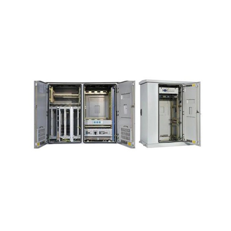
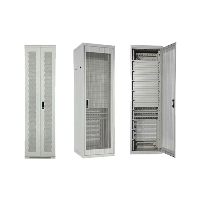
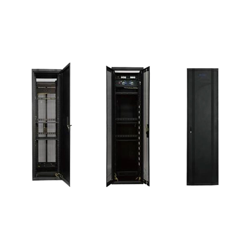
At this junction, the outdoor telecom cabinet copper to optical fiber replacement platform must accommodate the coexistence of both media during the transition period, while providing the termination, splicing, and distribution infrastructure that fibre requires and that copper cabinets were never designed to support. Fibre management demands are categorically different from copper cross-connection work: minimum bend radius requirements, fusion splice protection, and fibre tray organisation cannot be retrofitted into a cabinet designed around copper punch-down blocks and jumper routing without significant compromise to long-term serviceability.
Operators who attempt copper-to-fibre migration using repurposed copper cabinets consistently report higher splice failure rates and longer fault resolution times than those who deploy purpose-designed fibre distribution enclosures — an outcome that erodes the operational cost savings that fibre migration is intended to deliver.
Fibre Termination and Splice Management Inside the Street Cabinet
Fibre management inside an outdoor distribution cabinet involves a set of physical constraints that have no direct equivalent in copper cable handling. Single-mode fibre has a minimum bend radius of approximately 30 mm for standard G.652D cable under installation conditions and 15 mm in long-term static routing — radii that must be maintained throughout the cabinet's internal routing paths, splice tray organisation, and jumper storage loops. Violating these radii introduces microbend attenuation that degrades link performance progressively and is difficult to diagnose without optical time-domain reflectometer testing at the affected span.
Splice tray organisation within the cabinet follows a structured discipline that directly affects long-term maintenance efficiency. Each tray typically accommodates 12 or 24 fusion splices protected in individual heat-shrink sleeves, with the splice tray itself mounted on a swing-out or slide-out mechanism that allows access without disturbing adjacent trays. Wanma Technology's experience in optical communication network infrastructure — spanning passive optical components and field-deployed communication cabinets across national rail and urban transit systems — informs the practical standards that govern reliable long-term fibre management in outdoor enclosures.
- Fibre storage loops at cable entry points must provide sufficient slack to allow splice tray removal without tension on the cable sheath
- Fibre routing guides and D-rings must be spaced to prevent free-hanging sections that could be displaced during maintenance access
- Feeder and distribution fibres should be routed on separate sides of the cabinet to prevent cross-contamination during partial-cabinet work
- All splice trays should be individually labelled with the feeder cable, tube colour, and fibre number to enable fault isolation without tracing physical routes
Insertion loss budgets for FTTH deployments typically allow 0.1–0.2 dB per fusion splice, which means poor splice technique or inadequate fibre management that introduces mechanical stress on splice points can consume a significant portion of the available power budget before the signal reaches the customer premises equipment.
Managing the Coexistence Period: Hybrid Copper-Fibre Cabinet Configurations
Few operators complete a copper-to-fibre migration in a single cutover event. The practical reality is a transitional period — often spanning two to five years in large metropolitan access networks — during which the street cabinet must simultaneously support active copper subscribers on legacy DSL or PSTN services and fibre subscribers on GPON or active Ethernet platforms. This coexistence requirement places specific demands on cabinet internal organisation that purpose-built migration enclosures are designed to address.
The primary challenge is physical segregation. Copper cross-connection hardware, DSL splitter modules, and power feed equipment for remote line cards occupy different physical space and require different access frequencies than fibre splice trays and optical splitter cassettes. Intermingling these within a single unpartitioned cabinet interior creates a situation where routine copper maintenance work risks disturbing fibre components — a risk that is difficult to mitigate through technician training alone when time pressure and poor lighting are routine field conditions.
An outdoor telecom cabinet copper to optical fiber replacement solution that incorporates physical partitioning between the copper and fibre zones, with independent access doors for each zone where cabinet width permits, substantially reduces cross-contamination risk during the coexistence period. Partitioned hybrid cabinets have demonstrated 30–40% lower fibre-related incident rates during maintenance windows compared to unpartitioned hybrid configurations in access network operator studies of migration project outcomes.
Optical Splitter Placement Strategy and Its Effect on Downstream Network Flexibility
In passive optical network architectures, the location of the optical splitter — the passive component that divides a single feeder fibre signal into multiple distribution fibres — determines the topology of the downstream access network and has lasting implications for capacity upgrade paths. Centralised splitting, where all splitting occurs at the primary distribution cabinet closest to the optical line terminal, simplifies feeder cable management but limits the number of subscribers that can be served per feeder fibre to the splitter ratio at that single point.
Distributed splitting strategies — placing a first-level splitter at the primary distribution cabinet and second-level splitters in secondary cabinets or building entry points closer to subscribers — provide greater flexibility for serving areas with irregular subscriber density, reduce the per-subscriber fibre length on the distribution side, and allow capacity to be added by upgrading the second-level split ratio without replacing the feeder infrastructure. The trade-off is increased cabinet complexity and a higher total passive component count that must be managed across multiple field locations.
The cabinet infrastructure must support whichever splitting strategy is selected, which means splitter cassette mounting provisions, fibre routing capacity for the resulting port count, and connector panel organisation must all be dimensioned for the target split ratio at that cabinet location — not for the minimum initial deployment. Oversizing the splitter capacity at initial deployment is consistently more cost-effective than retrofitting additional tray capacity into a fully loaded cabinet during a subsequent network expansion programme.