

 English
 Français
 Español
 Português
 عربى





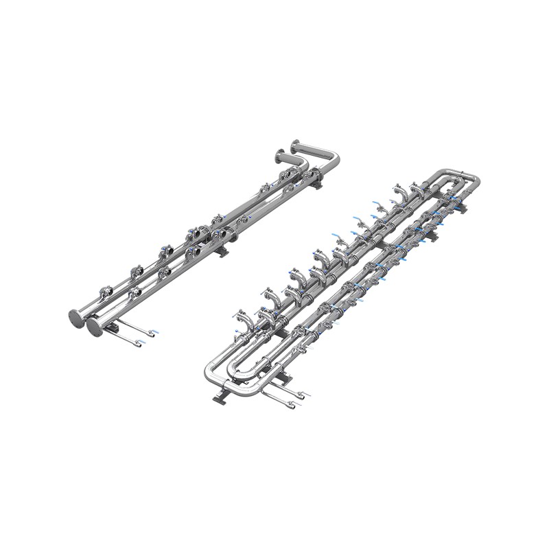
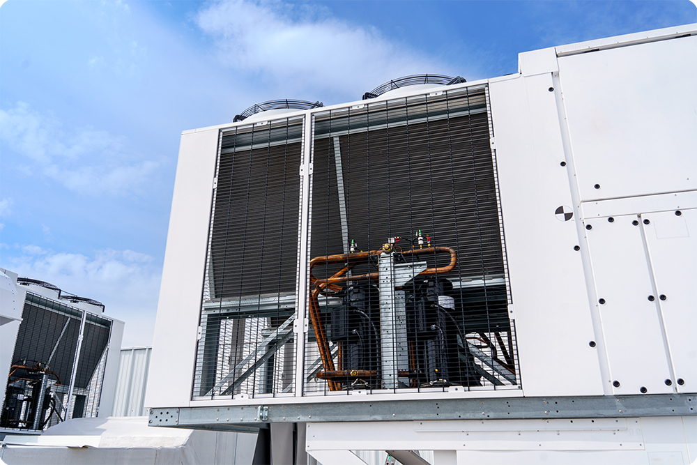
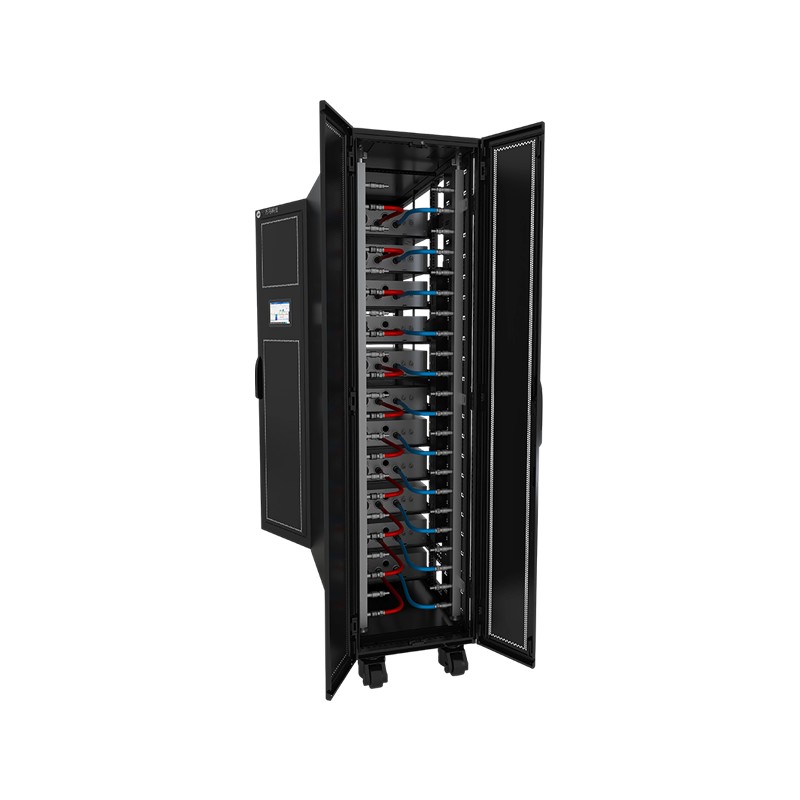
Product OverviewWM-SCL Secondary-Side Prefabricated Piping is a standardized coolant distribution system that connects the CDU to liquid-cooled server cabinets. The piping is prefabricated and quality...
See DetailsWhy Prefabricated Piping for Liquid Cooling Secondary Side Is Reshaping Data Center Deployment
Content
- 1 What Prefabricated Piping for Liquid Cooling Secondary Side Really Does
- 2 Why Factory Prefabrication Changes Secondary Loop Economics
- 3 Materials, Coolant Compatibility and Cleanliness Targets
- 4 Routing and Layout Decisions for CDU-to-Rack Connections
- 5 Online Maintenance Without Full-Loop Shutdown
- 6 Application Scenarios Across Data Center Types
- 7 A Planning Example for a Mid-Sized Liquid-Cooled Hall
- 8 Information to Prepare Before Engaging a Supplier
- 9 Frequently Asked Questions
- 9.0.1 Q1: What is prefabricated piping for liquid cooling secondary side used for?
- 9.0.2 Q2: Can the layout be adapted to a specific data hall?
- 9.0.3 Q3: Which coolants are typically compatible with stainless steel secondary loops?
- 9.0.4 Q4: Does a branch need a full loop shutdown for maintenance?
- 9.0.5 Q5: How should a team start the procurement discussion?
What Prefabricated Piping for Liquid Cooling Secondary Side Really Does
Liquid cooling has moved from a specialist option to a mainstream method for removing heat from dense computing hardware. In most facilities the cooling architecture is divided into a primary side and a secondary side. The secondary side carries conditioned coolant from a coolant distribution unit (CDU) to the cold plates inside server cabinets, and the pipework that forms this final connection is the subject of this guide. In practice, prefabricated piping for liquid cooling secondary side describes factory-assembled pipe modules that are designed, cut, cleaned, pressure tested and labeled before they reach the data hall.
The reason this matters is that the secondary loop is where most field risk accumulates. Every weld, joint and fitting assembled on a live site is a potential leak point, and every extra hour on site means more exposure to dust, moisture and schedule pressure. Moving that work into a controlled workshop changes the risk profile considerably, and it also changes who is accountable for quality.
Where the Secondary Loop Sits
A secondary loop typically begins at the CDU outlet, feeds a supply header that runs along a row of cabinets, branches into individual rack manifolds, and returns through a return header to the CDU inlet. Each stage carries different pressure, flow and cleanliness requirements, which is why the layout must be engineered as a complete system rather than a collection of pipe runs.
The diagram shows the basic topology. Supply and return headers are usually the largest-diameter runs, while branch lines are smaller and easier to isolate for service.
Core Components in a Typical Module
- Supply and return headers that distribute coolant evenly across the row.
- Branch assemblies with isolation valves at each rack connection point.
- Quick connection points sized to match the cabinet manifold interface.
- Optional sensor ports for flow, temperature, pressure and leak detection.
Why Factory Prefabrication Changes Secondary Loop Economics
Project teams often focus on the price of pipe and fittings, but the larger cost driver is usually time. Liquid-cooled halls are commissioned under tight schedules, and secondary loop work frequently sits on the critical path between mechanical completion and IT load-in. Prefabrication shortens that path by moving fabrication off site.
Integrators working on modular projects often report on-site labor reductions in the range of 30 to 50 percent when pipe assemblies arrive as tested modules. The exact figure depends on hall complexity, branch count and how early the layout is frozen, but the direction of the effect is consistent.
ControlledWorkshop fabrication and sealing
FasterShorter on-site installation window
RepeatableIdentical specification across modules
VerifiedPressure tested before shipment
Cleanliness Is Set in the Workshop
Debris left inside a coolant line can damage pumps, clog cold plate microchannels and trigger filter alarms long after commissioning. Site fabrication struggles to control this because cutting, grinding and welding generate particles in an uncontrolled environment. A workshop allows pipe ends to be capped, internal surfaces cleaned and assemblies flushed before they are sealed for transport.
Schedule Certainty
Prefabricated modules let the factory and the site work in parallel. While the factory builds and tests module sets, civil works, electrical rough-in and cabinet placement can proceed. When the modules arrive, installation becomes a matter of alignment and bolting rather than a sequence of hot-work tasks.
| Criteria | Site-erected piping | Prefabricated piping |
|---|---|---|
| Installation effort | High, sequential and labor-intensive | Lower, mainly alignment and bolting |
| Weld quality control | Depends on site conditions | Controlled in the workshop |
| Cleanliness | Harder to guarantee | Cleaned and capped before shipment |
| Pre-commissioning tests | Often performed after assembly | Completed module by module |
| Schedule exposure | Sensitive to weather and access | Runs in parallel with civil works |
| Later branch service | Depends on the original layout | Designed for isolation |
Materials, Coolant Compatibility and Cleanliness Targets
Material selection is one of the first decisions in any secondary loop. Austenitic stainless steel, commonly specified as S304, is widely used because it resists corrosion in typical data center coolant mixtures, holds dimensional stability and joins cleanly when the process is controlled. Gaskets, seals and sensor wetted parts must be checked against the same coolant chemistry, since a compatible pipe paired with an incompatible seal is a frequent source of field failures.
Coolant Options and Compatibility
Most secondary loops use deionized water, ethylene glycol or propylene glycol mixtures with corrosion inhibitors. Each option changes viscosity, heat transfer behavior and freezing point, so the design basis must state the concentration and the operating temperature window.
- Confirm wetted materials for pipe, fittings, gaskets and sensors against the specified coolant.
- Request the coolant supplier's compatibility data before final material approval.
- Record inhibitor type and concentration in the commissioning documentation.
- Plan periodic water quality sampling after handover.
Cleanliness Targets That Protect Equipment
Cleanliness is usually defined by a combination of particle count, filtration rating and visual inspection criteria agreed between the owner and the supplier. Setting these targets early in the design phase avoids disputes at commissioning.
Filtration at the CDU is not a substitute for clean pipework. Large debris introduced during installation can overload strainers and bypass fine filters during early operation.
Factory Test Sequence
- Dimensional check against the approved drawing and the rack interface.
- Internal cleaning and flushing, with verification of outlet cleanliness.
- Pressure hold test with documented pressure and duration.
- Leak inspection of every joint, flange and clamp.
- Protective capping, labeling and packing to prevent recontamination.
Each module ships with a traceable record, so the site team can confirm that what arrives matches what was tested.
Routing and Layout Decisions for CDU-to-Rack Connections
The quality of a CDU to rack prefabricated piping layout determines how evenly coolant reaches each cabinet. Routing that looks tidy on a plan can still create unequal flow if path lengths and fittings differ significantly between racks.
Hydraulic Balance Across Racks
A reverse-return arrangement, where the farthest cabinet on the supply side is the nearest on the return side, helps equalize path resistance without relying entirely on balancing valves. Balancing valves remain useful for fine tuning once actual rack loads are known, because loads in mixed-density halls rarely match the design estimate exactly.
Thermal Movement and Support
Stainless steel expands measurably as temperatures change. Long straight runs need fixed points and guided supports placed so that movement is absorbed at expansion features rather than at cabinet connections or the CDU. Support spacing should be checked against the weight of the coolant-filled pipe, not the empty pipe.
Service Access and Clearances
Branch valves and quick connection points must remain reachable with standard tools and without removing neighboring modules. Clearance zones in front of and behind cabinets should match the manufacturer's service envelope, and drip containment should sit under any joint that a technician might open.
| Design parameter | Recommended approach | Risk if ignored |
|---|---|---|
| Path length | Keep racks on similar path lengths | Uneven flow across the row |
| Isolation | One valve per branch | Full loop shutdown for service |
| Expansion | Guided supports and expansion features | Stress at cabinet connections |
| Access | Clear service envelope at every joint | Delays during maintenance |
Online Maintenance Without Full-Loop Shutdown
One of the most valuable features of a well-designed secondary-side liquid cooling piping system is the ability to service a single branch while the rest of the loop keeps running. Without that capability, a failed quick connect or a leaking sensor can force a shutdown of an entire row, which is expensive when the racks run production AI workloads.
The sequence shown above is simplified, and each site will adapt it to its own controls philosophy. The principle holds, though: isolate the branch, remove only the coolant that the branch holds, perform the work, and purge trapped air before reopening.
- Valves should be positioned so that a branch can be isolated without disturbing neighboring racks.
- Drain points should be sized to remove the branch volume efficiently and safely.
- Purge procedures must remove trapped air, which can otherwise cause flow instability.
- Maintenance procedures should be written before commissioning, not after the first incident.
Application Scenarios Across Data Center Types
The same secondary-side architecture adapts to several deployment models, although the emphasis shifts with rack density and project type.
AI training halls
High rack densities make short, well-balanced branches essential for stable flow.
HPC facilities
Long lifecycles favor serviceable branches and documented cleanliness records.
Containerized modules
Compact routing and factory testing suit transport and rapid site integration.
Retrofit projects
Prefabricated spools reduce disruption to adjacent live equipment during upgrades.
In retrofit work, the survey stage matters most. Existing routes, elevations and clearances are often inaccurate on legacy drawings, so laser scanning or detailed site measurement should precede any fabrication.
A Planning Example for a Mid-Sized Liquid-Cooled Hall
Consider an illustrative hall with sixteen liquid-cooled cabinets arranged in four rows and supplied by a single CDU group. A traditional approach would install supply and return headers on site, cut and join each branch, and test the loop after assembly. Each stage depends on the one before it, and a delay in one row can ripple through the whole schedule.
In a prefabricated approach, the design team freezes the layout first, then fabricates four row modules, each including its own supply and return sections and four branch assemblies. Modules are tested and capped in the workshop, shipped in sequence, and installed as the civil and electrical teams complete their work.
The benefit is not only speed. Fewer field operations reduce the number of hot-work permits, the amount of temporary protection needed and the chance that a late design change forces rework of joined sections. Teams also gain an earlier opportunity to test the design, because modules can be checked against the drawing before they leave the workshop.
Results will vary, but the planning principles are consistent: freeze cabinet positions early, define branch count and valve locations clearly, and agree on test criteria with all parties before fabrication begins.
Information to Prepare Before Engaging a Supplier
Clear inputs produce better shop drawings and fewer revisions. Teams that prepare the following information early usually move through design review faster.
- Hall layout drawings showing cabinet positions, spacing and row orientation.
- Cabinet count, manifold interface type and connection sizes.
- CDU location, port sizes and available elevation for headers.
- Coolant type, concentration and operating temperature window.
- Required monitoring points for flow, temperature, pressure and leak detection.
- Maintenance philosophy, including isolation and purge expectations.
- Site access constraints and delivery schedule.
Providing this information at the start allows a supplier to propose a practical arrangement, identify conflicts with other trades and agree on test documentation. It also helps the owner compare options on a like-for-like basis.
Frequently Asked Questions
Q1: What is prefabricated piping for liquid cooling secondary side used for?
It connects the coolant distribution unit to the liquid-cooled server cabinets on the secondary loop, delivering conditioned coolant through factory-built modules that are cleaned and tested before installation.
Q2: Can the layout be adapted to a specific data hall?
Yes. Routing, header sizes, branch counts and connection types are normally defined from the hall drawings, cabinet positions and coolant requirements, so the final assembly matches the actual site rather than a generic template.
Q3: Which coolants are typically compatible with stainless steel secondary loops?
Deionized water and common glycol mixtures with corrosion inhibitors are typical choices. Compatibility of gaskets, seals and sensors should be verified against the chosen coolant and its supplier documentation.
Q4: Does a branch need a full loop shutdown for maintenance?
A properly designed system isolates each branch with its own valves and drain points, so a single rack connection can be serviced while the rest of the loop continues operating.
Q5: How should a team start the procurement discussion?
Begin with the information listed above, then request a technical review and a draft layout. A clear brief allows suppliers to return a realistic scope, a drawing package and a quotation without multiple rounds of clarification.
PREV:What Causes Self-Sealing Quick Couplers and Hoses to Fail and How to Maintain Them
NEXT:How to Select Quick Couplers and Hoses for Data Center Liquid Cooling Systems
NEXT:How to Select Quick Couplers and Hoses for Data Center Liquid Cooling Systems
Interested in cooperation or have questions?
Related products
-
-
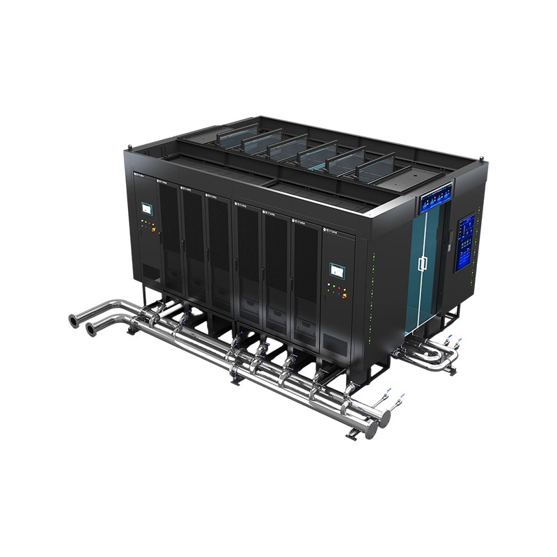
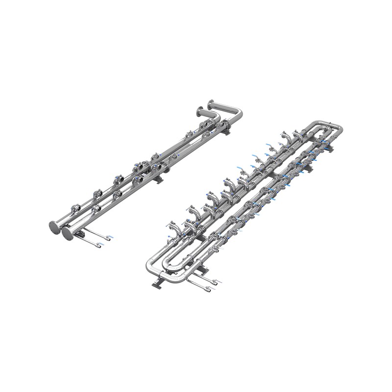
Product OverviewWM-HCM Air-Liquid Hybrid Micro-Module is an integrated data center solution designed for ultra-high-density computing applications. It adopts a dual-row, back-to-back layout and integr...
See Details -
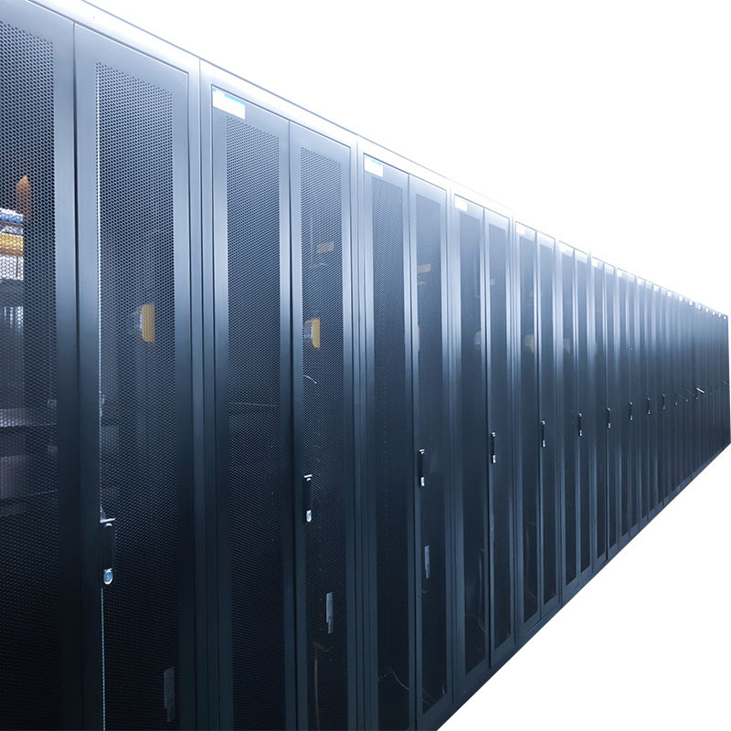
Application:It is used in internet data center equipment room to house server cabinets and provides them with required working environment. Features:•Modularization: Two cabinets combined sharing one ...
See Details -
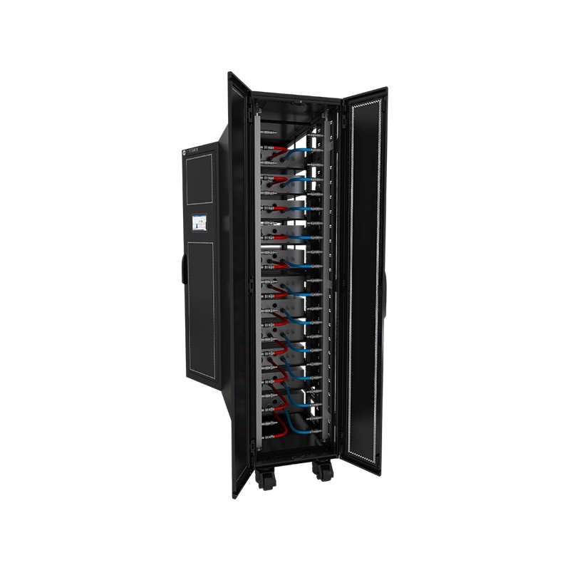
Product OverviewWM-LCR Liquid-Cooled Server Cabinet is a dedicated data center cabinet system that uses liquid as the cooling medium. Through circulating coolant, it efficiently transfers heat generat...
See Details
Ready to Get started ? Contact Us Now !

Product.
Contact Details.
-
 +86 13958188250
-
 +86 13958188250
-
 [email protected]
-
 AUDIT Email:[email protected]
- Wanma Industrial Park Taihu Yuan Town Lin'an District Hangzhou City China.
QR Code

Copyright © Wanma Technology Co., Ltd. All Rights Reserved.
Privacy
Custom Ethernet Optical Network Railway Transit Equipments Suppliers
