

 English
 Français
 Español
 Português
 عربى
عربى



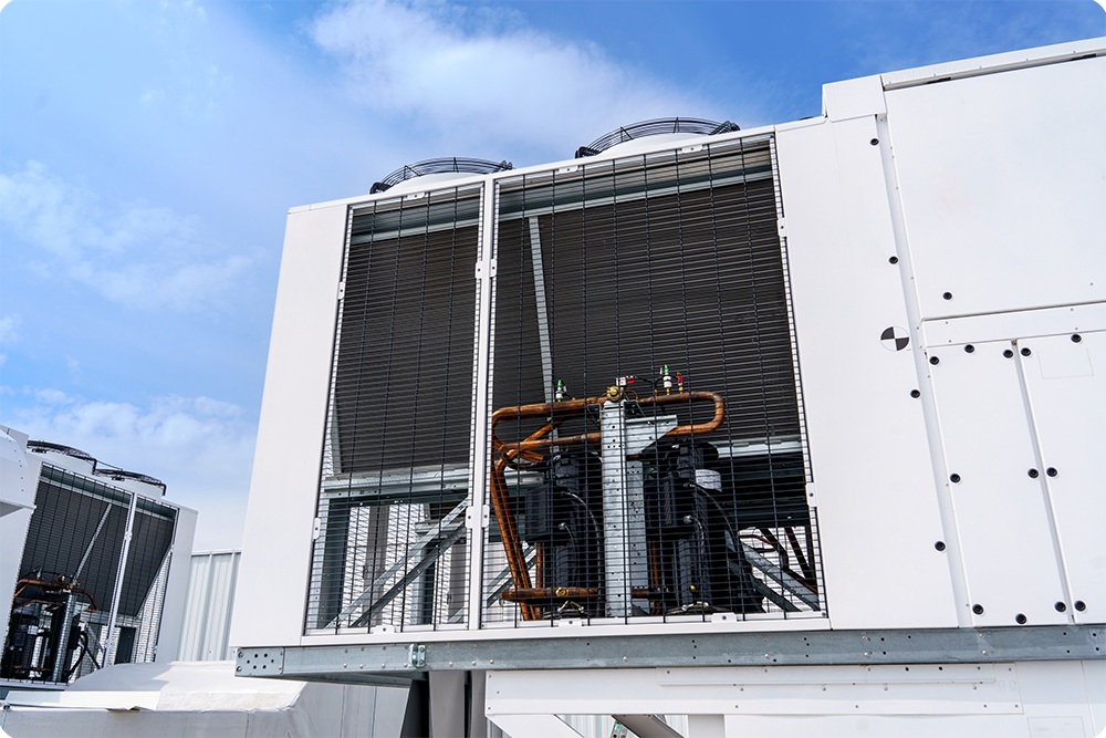
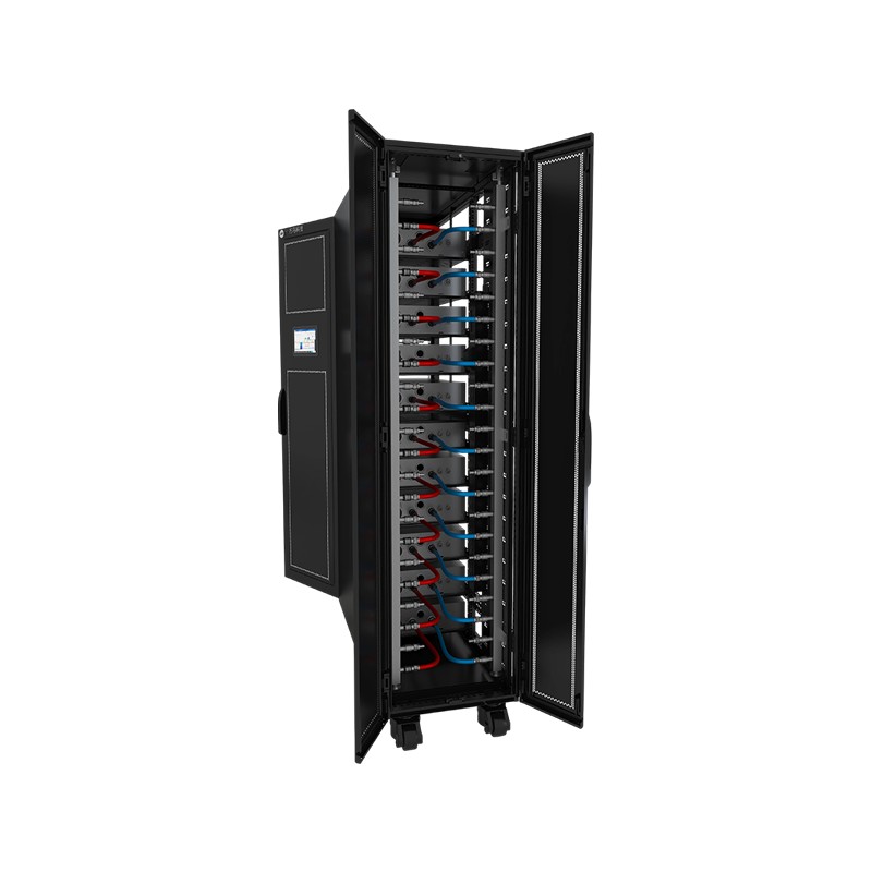
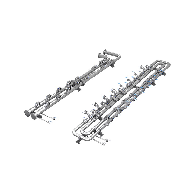
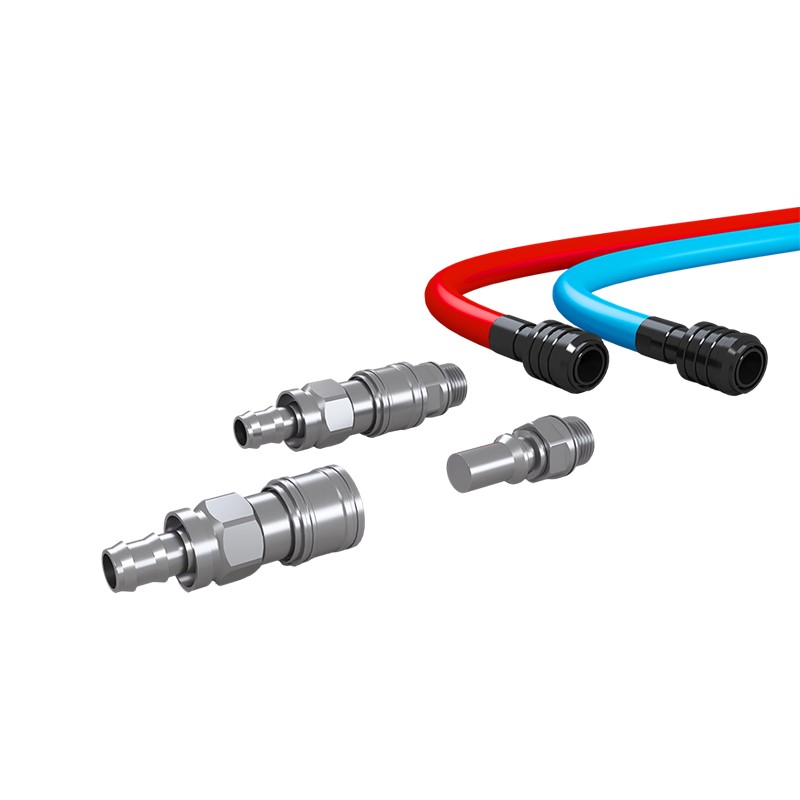
Product OverviewWM-SCL Secondary-Side Prefabricated Piping is a standardized coolant distribution system that connects the CDU to liquid-cooled server cabinets. The piping is prefabricated and quality...
See DetailsLiquid-Cooling Products: The Complete Guide for AI Data Center Infrastructure
Content
- 1 Why Liquid Cooling Has Become Infrastructure Imperative
- 2 The Complete Spectrum of Liquid-Cooling Products for High-Density Infrastructure
- 3 How to Select the Right Liquid-Cooling Products for Your Infrastructure
- 4 Why In-House Development Defines Superior Liquid-Cooling Products
- 5 Strategic Deployment Patterns for Scaling Liquid-Cooling Infrastructure
- 6 Comparative Thermal Efficiency Analysis
- 7 Decision Framework for Evaluating Liquid-Cooling Product Providers
- 8 Implementation Roadmap: From Planning to Production Operations
- 9 Frequently Asked Questions About Liquid-Cooling Products
- 9.0.1 Q1: What are the primary types of liquid-cooling products used in modern data centers?
- 9.0.2 Q2: How do I determine whether cabinet-mount or rack-mount CDU configurations best suit my facility?
- 9.0.3 Q3: Can existing air-cooled data centers retrofit liquid-cooling products without complete infrastructure replacement?
- 9.0.4 Q4: What lead times should I anticipate for pre-fabricated liquid-cooling product systems?
- 9.0.5 Q5: How do monitoring systems integrate with facility management platforms when deploying liquid-cooling products?
- 9.0.6 Q6: What maintenance procedures should I implement for liquid-cooling product systems?
- 9.0.7 Q7: How do liquid-cooling products support sustainability and environmental compliance objectives?
- 10 Engage with Thermal Infrastructure Expertise
The computational demands of modern artificial intelligence have fundamentally transformed data center thermal management. GPU clusters and accelerator-dense server configurations now routinely exceed 700 watts of power per chip, pushing traditional air-cooling architectures beyond their physical limits. The global market for data center liquid-cooling products reflects this urgency: projected growth from USD 4.07 billion in 2026 to USD 27.65 billion by 2033, representing a compound annual growth rate of 31.5 percent. This expansion signals not merely a trend, but a fundamental shift in how organizations architect their computational infrastructure. Modern liquid-cooling products represent the convergence of engineering precision, factory-scale quality assurance, and modular deployment philosophy—enabling data center operators to achieve unprecedented thermal density while reducing cooling energy consumption by up to 90 percent compared to air-cooled baselines.
Why Liquid Cooling Has Become Infrastructure Imperative
Air-cooling technologies encounter three critical failure scenarios in contemporary data center environments. First, when single-rack power densities exceed 20 kilowatts, traditional overhead Computer Room Air Handling units struggle to maintain inlet temperatures within acceptable ranges without consuming prohibitive quantities of facility energy. Second, large GPU compute clusters generate thermal hotspots that air recirculation systems cannot effectively address, leading to thermal throttling and reduced computational efficiency. Third, the energy cost of maintaining sub-30-degree-Celsius inlet air in high-density racks creates an unsustainable power usage effectiveness ceiling.
Liquid-cooling systems address these constraints through superior thermal conductivity. Water absorbs heat approximately 4,000 times more effectively than air at equivalent flow rates, enabling dramatic reductions in coolant volume requirements. A well-designed liquid cooling infrastructure can reduce overall data center cooling energy expenditure by 60 to 90 percent, directly improving the Power Usage Effectiveness metric that governs operational cost models. This efficiency gain extends facility lifespan, reduces water consumption per computational unit, and aligns infrastructure investment with corporate sustainability mandates. Selecting appropriate liquid-cooling products therefore represents both a technical necessity and a strategic business decision for organizations managing large-scale AI workloads.
The Complete Spectrum of Liquid-Cooling Products for High-Density Infrastructure
Cabinet-Mount and Rack-Mount Cooling Distribution Units
Cooling Distribution Units, commonly abbreviated CDU, function as the circulatory heart of any liquid-cooling architecture. These units perform three essential operations: receiving heated return liquid from server components, transferring that thermal energy to facility cooling loops or external heat rejection systems, and redistributing cooled liquid to computing equipment. Modern cabinet-mount CDU designs integrate multiple redundancy layers, pressure-relief mechanisms, and real-time fluid temperature and flow-rate monitoring. Factory pressure-testing protocols—typically conducted at 1.5 times maximum operating pressure—ensure system integrity before shipment. Integrated leak detection systems provide millisecond-scale response times, triggering electromagnetic shutoff valves to prevent catastrophic fluid loss. The engineering discipline applied to CDU manufacturing distinguishes professional-grade liquid cooling from hastily assembled alternatives.
Liquid-Cooled Server Cabinet Systems
Complete cabinet-level solutions represent the next evolutionary step beyond component-level CDU integration. These architectures bundle chassis, liquid distribution manifolds, quick-disconnect couplings, and temperature control logic into unified factory-pre-assembled packages. Modular design philosophy permits organizations to scale incrementally: a 10-rack deployment can expand to 50 racks without requiring wholesale reconfiguration of the underlying cooling substrate. Many modern cabinet systems support air-liquid hybrid deployment scenarios, where non-accelerator components (storage controllers, network switching fabric) remain air-cooled while GPU and CPU elements utilize direct-to-chip liquid contact. This heterogeneous approach reduces total system cost while maximizing the thermal density benefits of targeted liquid cooling application.
Manifolds and Quick-Disconnect Couplings
The secondary-side fluid distribution network—the interconnect infrastructure between cabinet-resident CDUs and individual compute nodes—depends entirely on manifold and coupling quality. Manifolds consolidate multiple inlet and outlet streams into unified ports, reducing installation complexity and leak surface area. Quick-disconnect couplings enable maintenance operations without system shutdown: a technician can safely isolate a failed server component, disconnect its thermal lines, replace the unit, and reconnect with zero minutes of cooling system downtime. These couplings incorporate internal check-valves that prevent backflow during disconnection and minimize residual fluid loss. Flat-face designs, now industry standard, reduce spillage to less than 5 milliliters per disconnection cycle—enabling maintenance activities in sensitive environments without towel requirements or environmental concerns.
Pre-Fabricated Piping and Micro-Module Assemblies
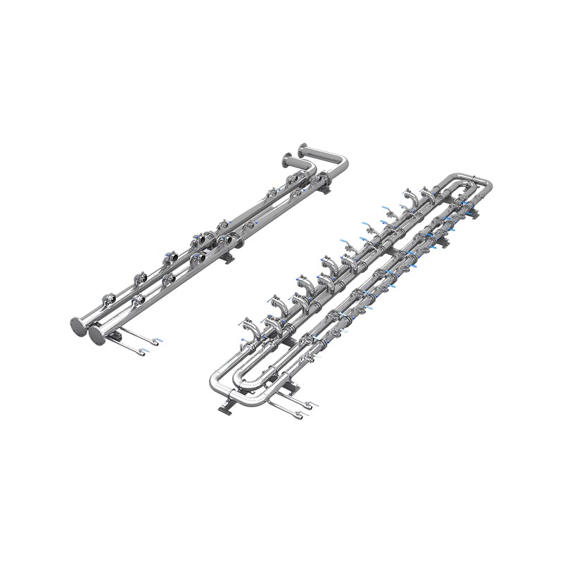
Installation duration represents a frequently underestimated cost component in data center deployment projects. Traditional site-built piping—where technicians assemble copper tubing, hand-braze connections, and pressure-test systems onsite—introduces weeks of project delay and substantial quality variability. Pre-fabricated piping systems, manufactured under factory climate control with automated joining processes and comprehensive NDT (non-destructive testing) protocols, eliminate this risk category entirely. Micro-module assemblies bundle pre-fabricated thermal pipes, integrated pumps, expansion tanks, and manifold structures into single arrived-ready configurations. A data center facility can receive a pre-fabricated micro-module, integrate it into the cabinet infrastructure via quick-disconnects, verify connections, and place it into service within hours rather than weeks.
Modular Scaling and Custom Configuration Architecture
Heterogeneous AI workloads demand customizable liquid-cooling strategies. Some organizations deploy high-capacity CDUs capable of supporting 15 to 20 kilowatts of thermal rejection per unit; others require smaller distributed units to service mixed-density racks. Quick-disconnect architecture enables this flexibility: racks can be configured with different CDU capacities, interconnected via standardized couplings, and managed through unified monitoring systems. Expansion scenarios—growing from 20 to 50 racks over 18 months—proceed without disrupting existing installations. This modular philosophy transforms liquid cooling from a fixed infrastructure decision into a scalable, incrementally upgradeable deployment model.
How to Select the Right Liquid-Cooling Products for Your Infrastructure
Systematic product selection requires evaluating several interdependent parameters. First, calculate required coolant flow rate based on computing power: industry guidelines recommend approximately 1.5 liters per minute for each kilowatt of thermal load. A rack supporting 30 kilowatts therefore requires CDU capacity of 45 liters per minute minimum. Second, assess pressure drop across the complete fluid circuit: higher flow rates demand more powerful circulation pumps, consuming facility electrical capacity. Third, evaluate heat exchanger approach temperature—the differential between returning hot liquid and facility coolant supply. Smaller approach temperatures require larger, more expensive heat exchangers but deliver superior efficiency.
Facility compatibility assessment follows. Verify water availability and quality: many installations utilize facility chilled water loops, requiring compatibility with existing Treatment and monitoring systems. Assess available floor space within server cabinets and racks, accounting for CDU physical dimensions plus maintenance access corridors. Review existing facility power distribution: pump motors consume 3 to 7 kilowatts depending on flow requirements and pressure specs. Confirm HVAC system capability to handle latent cooling load from liquid-cooled cabinets, since improved computing efficiency reduces overall facility cooling demand but concentrates remaining load in specific zones.
Redundancy and maintainability considerations prove equally critical. Pump redundancy—dual pumps with automatic failover—ensures cooling continuity during maintenance or component failure. Front-access manifold and coupling design permits technician work from the cabinet front without requiring rear-space access. Verify monitoring system compatibility: modern data center management platforms require Redfish, Modbus, or BACnet protocol support for automated alerting when flow rates, pressures, or temperatures drift outside acceptable ranges. Thermal imaging integration enables rapid fault isolation when performance degrades.
| Selection Criterion | Typical Industry Standard | Advanced Configuration |
|---|---|---|
| Flow Rate (LPM per kW) | 1.5 | 1.0-1.3 (optimized) |
| Heat Exchanger Approach | 5-8°C | 3-5°C |
| Pump Redundancy | Single pump | Dual pump with failover |
| Maintenance Access | Rear access preferred | Front and rear options |
| Monitoring Integration | Basic alerts | Full protocol suite (Redfish/Modbus/BACnet) |
Why In-House Development Defines Superior Liquid-Cooling Products
The market for cooling infrastructure encompasses two fundamentally different value propositions: system integrators and product developers. Integrators source components from multiple suppliers—pumps from manufacturer A, manifolds from manufacturer B, quick-disconnects from manufacturer C—then assemble these elements into customer solutions. While this approach offers flexibility, it inherently introduces variability: component tolerances stack, communication interfaces require translation layers, and warranty responsibility fragments across supplier boundaries. Any system failure triggers supplier finger-pointing rather than rapid resolution.
Fully in-house developed liquid-cooling products eliminate these integration complexities. Design teams control every element simultaneously: pump selection, manifold geometry, quick-disconnect specifications, and control software all evolve as an integrated system rather than independent components. Factory manufacturing permits application of consistent quality standards across all production units. Pressure-testing protocols validate complete assemblies under worst-case thermal load conditions before shipment. Design teams maintain intimate familiarity with failure modes and edge cases, enabling rapid troubleshooting when field issues emerge. One-stop technical support—from initial selection consultation through long-term maintenance partnerships—transforms cooling infrastructure from a vendor-managed commodity into a trusted infrastructure partner relationship.
Sustainability integration exemplifies this advantage. In-house teams can implement comprehensive fluid lifecycle management: closed-loop recycling systems, biodegradable coolant options, and minimal-waste manufacturing processes that reflect organizational environmental commitments. Custom configuration capabilities enable precise capacity matching, eliminating oversized equipment that consumes unnecessary energy. Modular architecture supports infrastructure extension without wholesale replacement, reducing e-waste and raw material consumption across a facility's multi-decade operational lifespan.
Strategic Deployment Patterns for Scaling Liquid-Cooling Infrastructure
Single-Rack Pilot Deployments
Organizations frequently begin liquid-cooling adoption with 1 to 3 rack pilots, validating thermal performance, operational procedures, and facility integration before broader rollout. Pilot deployments surface integration challenges—power distribution constraints, chilled water loop compatibility, monitoring system connectivity—that theoretical analysis cannot predict. A well-designed pilot architecture includes all infrastructure elements present in full-scale deployments: redundant CDUs, complete quick-disconnect networks, and unified monitoring systems. This approach transforms the pilot from a proof-of-concept into a production-ready reference configuration, enabling rapid replication across additional racks as confidence builds.
Heterogeneous Rack Configurations
Large facilities rarely achieve uniform computing configurations. Some racks prioritize GPU acceleration for large language model inference; others emphasize CPU-dense workloads requiring different thermal profiles. Modular liquid-cooling products accommodate this heterogeneity: a facility can deploy 10-kilowatt CDUs in storage-focused racks, 20-kilowatt units in GPU-dense configurations, and 15-kilowatt intermediate units in mixed workload racks. Quick-disconnect standardization enables technicians to swap CDU capacity without replacing entire cabinet assemblies, adapting infrastructure as workload distributions evolve over facility lifetime.
Chilled Water Integration
Facilities with existing central chilled water systems can integrate liquid-cooling products through facility heat exchanger connections. Rather than deploying independent CDU cooling loops, system designers can specify heat exchangers that interface cabinet-level coolant circuits to existing facility water infrastructure. This integration approach reduces total system capital cost, leverages existing facility energy investments, and simplifies monitoring through unified facility control systems. Integration complexity depends on facility water quality standards, so early collaboration between data center engineering and cooling infrastructure teams proves essential.
Incremental Capacity Expansion
Computational demands rarely increase uniformly. Organizations typically grow from 20 racks of capacity to 50 racks over 18 to 24 months. Pre-fabricated, modular liquid-cooling products enable this incremental scaling without disrupting existing operations: new cabinet units arrive at the facility, integrate via quick-disconnects into existing coolant distribution networks, and come online within hours. This staged capacity deployment approach spreads capital investment across fiscal periods, manages facility infrastructure complexity incrementally, and permits operational staff to master cooling system management gradually before handling larger installations.
Comparative Thermal Efficiency Analysis
Decision Framework for Evaluating Liquid-Cooling Product Providers
Engineering Capability Assessment
Evaluate whether the supplier has demonstrated capability in the following domains: thermal modeling and simulation, pressure-drop analysis, reliability engineering with failure-mode analysis, and control system integration. Organizations should request detailed technical documentation—heat transfer calculations, pump sizing rationale, cooling circuit redundancy specifications. These materials reflect engineering depth and enable independent verification of claimed performance characteristics.
Manufacturing Quality Standards
Factory certifications provide baseline confidence but do not guarantee product excellence. Request information about non-destructive testing protocols applied to pressure boundaries, leak detection methodologies, and long-duration thermal stress testing. Ask whether production units undergo 100 percent pressure testing or statistical sampling. Inquire about material traceability: can the supplier document welding procedures, heat treatment processes, and material certifications for every pressure-containing component? These process controls distinguish disciplined manufacturing from quantity-focused assembly operations.
Technical Support and Long-Term Partnership
Thermal infrastructure failures can cascade rapidly if not addressed immediately. Evaluate whether suppliers provide 24/7 technical escalation, on-site support options for critical deployments, and detailed troubleshooting documentation. Request references from facilities of similar scale and workload profile; contact these references directly to understand support responsiveness and problem-resolution effectiveness. Organizations should prioritize providers who view themselves as long-term infrastructure partners rather than transactional component vendors.
Customization Flexibility and Roadmap Alignment
AI workload requirements evolve rapidly. Suppliers should demonstrate willingness to customize configurations, adapt thermal capacities to changing needs, and evolve products as new computational platforms emerge. Request information about product roadmaps: are new quick-disconnect standards being adopted? Are monitoring system integrations expanding to additional platforms? Does the supplier participate in industry consortium work on thermal management standardization? Forward-looking partnership orientation predicts long-term value delivery.
Implementation Roadmap: From Planning to Production Operations
Phase 1: Infrastructure Assessment and Thermal Modeling (4-8 weeks)
Begin with comprehensive facility analysis: measure rack power densities, assess chilled water availability and temperature targets, document electrical distribution capacity, and photograph cable management constraints. Develop thermal models projecting computing power evolution across the next 18-24 months. Identify where liquid cooling will concentrate—GPU-dense racks are highest-priority targets; secondary optimization addresses CPU-heavy configurations. This modeling work informs CDU sizing and cabinet configuration decisions, preventing over-provisioning or undersizing scenarios that generate future regret.
Phase 2: Pilot Configuration and Testing (8-12 weeks)
Deploy 1 to 3 representative racks with production liquid-cooling products, complete quick-disconnect networks, and unified monitoring systems. Operate the pilot at full thermal load for minimum 500 hours, documenting temperature stability, power consumption, pressure differentials, and alerting system responsiveness. Train facility operations staff on coolant level checks, quick-disconnect disconnection procedures, temperature trending analysis, and basic troubleshooting. Address any configuration issues discovered during pilot operation before committing to facility-wide deployment.
Phase 3: Facility-Scale Deployment Planning (4-6 weeks)
Develop comprehensive deployment schedules accounting for existing workload continuity requirements. Many facilities operate in 24/7 production environments without shutdown windows; deployment planning must identify maintenance windows or accept staged rack transitions over several months. Coordinate with facility management regarding chilled water loop modifications, electrical panel upgrades, and monitoring system integration. Establish spare parts inventory covering quick-disconnects, pump assemblies, pressure relief valves, and expansion tank components.
Phase 4: Production Rollout and Optimization (ongoing)
Execute deployment according to schedules, validating each rack configuration before placing into production service. Implement performance monitoring dashboards tracking coolant flow rates, temperature differentials, power consumption, and computational throughput. Establish preventive maintenance schedules: fluid analysis on regular intervals, heat exchanger inspection procedures, pump bearing inspection routines. Over 12 to 24 months, gradually optimize operational parameters: increase flow rates to reduce pump power consumption, lower inlet temperatures to boost computational performance, or adjust redundancy configurations based on observed failure patterns. Data-driven continuous improvement transforms initial deployments into genuinely optimized infrastructure.
Frequently Asked Questions About Liquid-Cooling Products
Q1: What are the primary types of liquid-cooling products used in modern data centers?
Three primary product categories define contemporary data center thermal infrastructure. Cooling Distribution Units manage coolant circulation, heat exchange, and pressure regulation. Cabinet-level integration systems bundle CDUs, manifolds, and monitoring into pre-assembled packages. Quick-disconnect couplings and pre-fabricated piping minimize installation complexity and enable maintenance without thermal load interruption. These components combine into complete thermal management ecosystems supporting everything from single-rack pilots to facility-scale deployments.
Q2: How do I determine whether cabinet-mount or rack-mount CDU configurations best suit my facility?
Cabinet-mount units occupy space within the equipment cabinet itself, minimizing facility footprint but potentially constraining component arrangement. Rack-mount configurations occupy dedicated positions in the equipment rack, slightly reducing server component capacity but simplifying thermal circuit architecture. The optimal choice depends on physical dimensions available, planned thermal load per cabinet, and maintenance accessibility requirements. Facilities with space constraints typically favor cabinet-mount solutions, while those with larger cabinet footprints may prefer rack-mount standardization. Consult with engineering teams familiar with your specific equipment configurations and facility constraints.
Q3: Can existing air-cooled data centers retrofit liquid-cooling products without complete infrastructure replacement?
Yes, retrofit scenarios represent a common transition path. Organizations typically begin with 1 to 3 racks of liquid cooling, validating operational procedures and facility integration before broader deployment. Pre-fabricated manifolds and quick-disconnect standardization enable incremental cabinet transitions, avoiding wholesale facility redesign. Over 12 to 24 months, facilities can gradually transition high-thermal-density racks to liquid cooling while maintaining air cooling for remaining infrastructure. This phased approach spreads capital investment across fiscal periods and permits operational staff to master cooling system management progressively.
Q4: What lead times should I anticipate for pre-fabricated liquid-cooling product systems?
Lead times vary significantly based on configuration complexity and supplier production capacity. Standard catalog configurations typically ship within 6 to 8 weeks, permitting planning cycles aligned with most facility budgeting timeframes. Custom configurations requiring specialized manifold geometry, non-standard quick-disconnect arrangements, or integration with proprietary monitoring systems may extend to 12 to 16 weeks. Organizations should initiate supplier engagement and specification work during facility thermal modeling phases, permitting parallel execution of design and manufacturing activities that compress total project timelines.
Q5: How do monitoring systems integrate with facility management platforms when deploying liquid-cooling products?
Modern cooling infrastructure supports Redfish, Modbus, and BACnet protocols enabling integration with existing data center operations platforms. Temperature sensors, pressure transducers, and flow meters report into unified dashboards providing real-time system status and historical trending capabilities. Automated alerting triggers when parameters drift outside acceptable ranges, enabling proactive technician response before thermal emergencies develop. Advanced integrations correlate cooling system metrics with computational performance data, identifying opportunities to optimize inlet temperatures or pump speeds based on observed workload patterns.
Q6: What maintenance procedures should I implement for liquid-cooling product systems?
Preventive maintenance encompasses several critical activities. Quarterly fluid analysis programs monitor contamination levels and thermal properties, ensuring cooling efficiency remains within design parameters. Annual heat exchanger inspections identify scaling or fouling that might reduce thermal effectiveness. Pump bearing inspections occur every 18 to 24 months, identifying wear patterns before catastrophic failure. Quick-disconnect coupling maintenance involves verification of check-valve operation and cleanliness of contact surfaces. Organizations should establish detailed preventive maintenance schedules tailored to their specific facility conditions, coolant chemistry, and operational intensity patterns.
Q7: How do liquid-cooling products support sustainability and environmental compliance objectives?
Liquid-cooling systems reduce data center cooling energy consumption by 60 to 90 percent compared to traditional air cooling, directly supporting corporate decarbonization objectives. Modular architecture enables precise capacity matching, preventing oversized equipment that consumes unnecessary energy across infrastructure lifetime. Closed-loop coolant systems minimize water consumption compared to cooling towers requiring continuous evaporative losses. Advanced liquid-cooling products utilize biodegradable thermal fluids compatible with environmental protection standards, eliminating hazardous substance concerns. Organizations pursuing net-zero energy operations or Science-Based Targets climate commitments should prioritize liquid-cooling infrastructure development as a core decarbonization strategy.
Engage with Thermal Infrastructure Expertise
Selecting appropriate liquid-cooling products requires sophisticated technical evaluation, facility-specific customization, and partnership with suppliers capable of supporting long-term infrastructure operations. Organizations implementing AI and high-performance computing workloads should begin infrastructure assessment immediately: thermal modeling work typically requires 4 to 8 weeks, providing ample time for supplier evaluation and configuration planning. Request detailed technical documentation, engineer-to-engineer consultation opportunities, and facility references from comparable deployment scenarios. Request a product selection guide outlining configuration options matched to your specific thermal requirements, facility constraints, and deployment timeline objectives. Infrastructure decisions made today will govern computational efficiency and operational costs across the next decade—deliberate, data-driven vendor selection yields dividends across entire facility lifespan.
PREV:Why Liquid Cooling Manifolds Have Become the Hidden Bottleneck in Modern AI Infrastructure
NEXT:How Cabinet CDU Transforms Thermal Management in AI and High-Density Computing Environments
NEXT:How Cabinet CDU Transforms Thermal Management in AI and High-Density Computing Environments
Interested in cooperation or have questions?
Related products
-
-
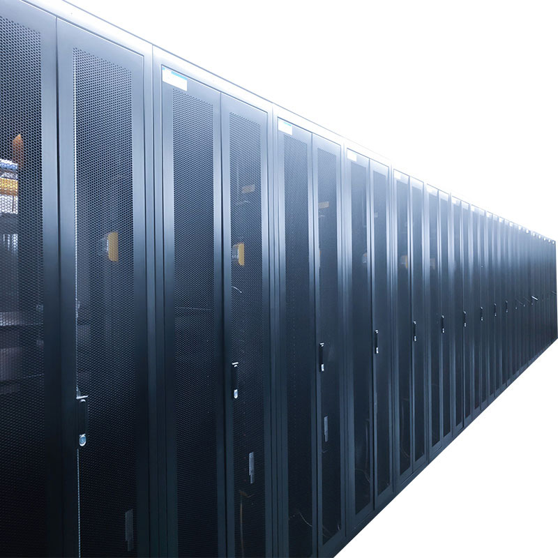
Application:It is used in internet data center equipment room to house server cabinets and provides them with required working environment. Features:•Modularization: Two cabinets combined sharing one ...
See Details -

A micro-module data center (MMDC) is a new generation data center architecture that uses standardized modules as units, features prefabricated design, and allows for rapid deployment. It integrates t...
See Details -
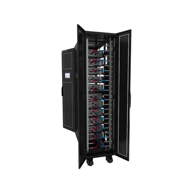
Product OverviewWM-LCR Liquid-Cooled Server Cabinet is a dedicated data center cabinet system that uses liquid as the cooling medium. Through circulating coolant, it efficiently transfers heat generat...
See Details
Ready to Get started ? Contact Us Now !

Product.
Contact Details.
-
 +86 13958188250
-
 +86 13958188250
-
 [email protected]
- Wanma Industrial Park Taihu Yuan Town Lin'an District Hangzhou City China.
QR Code

Copyright © Wanma Technology Co., Ltd. All Rights Reserved.
Privacy
Custom Ethernet Optical Network Railway Transit Equipments Suppliers
