

 English
 Français
 Español
 Português
 عربى
عربى



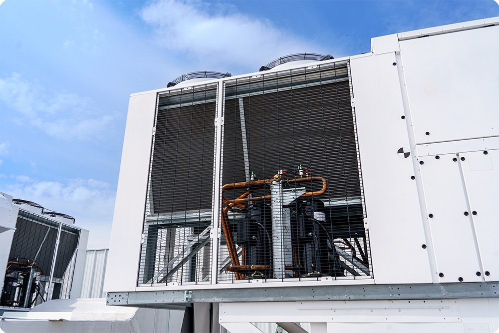
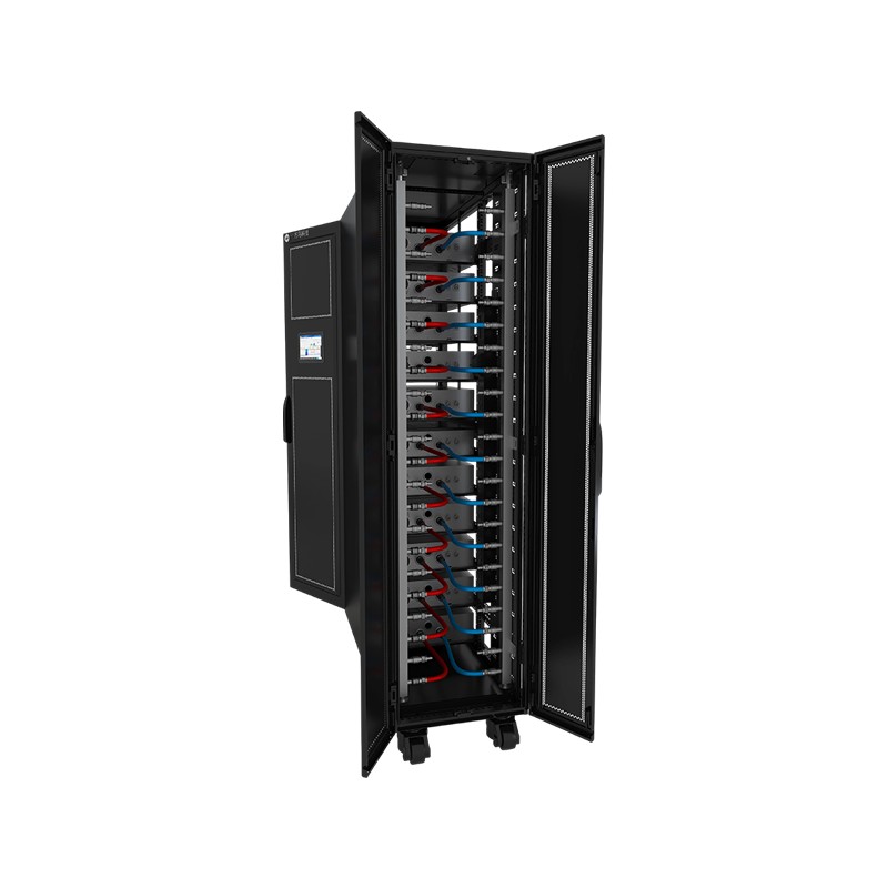
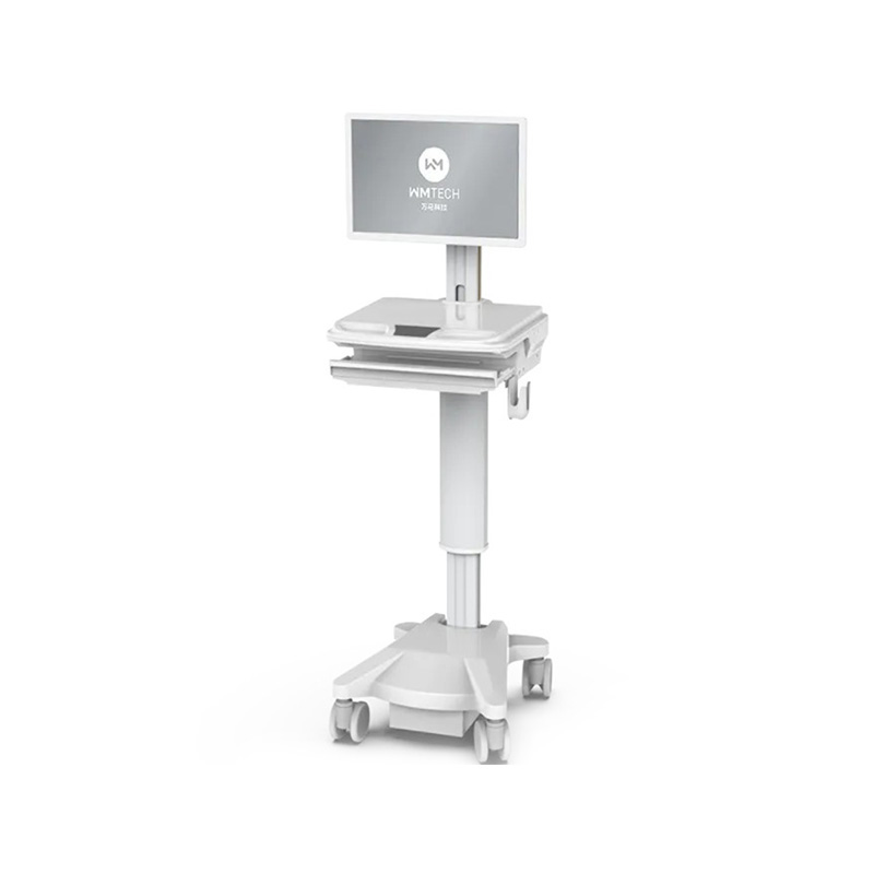
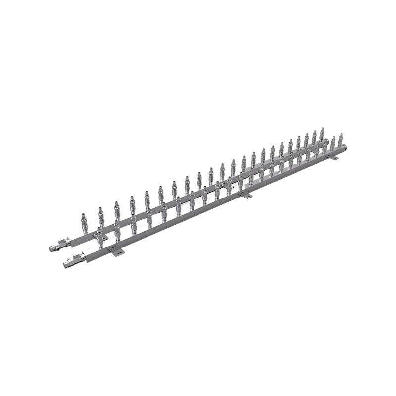
Product OverviewWM-HCM Air-Liquid Hybrid Micro-Module is an integrated data center solution designed for ultra-high-density computing applications. It adopts a dual-row, back-to-back layout and integr...
See DetailsWhy Liquid Cooling Manifolds Have Become the Hidden Bottleneck in Modern AI Infrastructure
Content
- 1 The Manifold's Unexpected Moment: From Commodity to Critical Infrastructure
- 2 The Engineering Bar: What Modern Manifolds Must Deliver
- 3 Supply-Demand Misalignment: Why Precision Manifolds Have Become Scarce
- 4 Divergent Strategies in Manifold Engineering: Material Routes and Market Segmentation
- 5 Manifold Performance Impact: How Distribution Efficiency Shapes Data Center Economics
- 6 Selecting Manifolds for Mission-Critical Deployments: What Data Center Architects Should Evaluate
- 7 The Manifold Market Trajectory: What to Expect Through 2027 and Beyond
- 8 Best Practices for Manifold Procurement and Deployment
- 9 Conclusion: Why Manifolds Matter in the Age of Liquid Cooling
- 10 Frequently Asked Questions
- 10.0.1 Q1: What exactly is a liquid cooling manifold?
- 10.0.2 Q2: Why have manifolds become difficult to source in 2026?
- 10.0.3 Q3: What flow uniformity standard should I require from manifold suppliers?
- 10.0.4 Q4: How do I know if a manifold is compatible with my existing cooling infrastructure?
- 10.0.5 Q5: What's the difference between metal and polymer manifold designs?
- 10.0.6 Q6: How often should manifold seals and couplers be replaced?
- 10.0.7 Q7: Can I retrofit an air-cooled data center with manifold-based liquid cooling?
- 10.0.8 Q8: What happens if a manifold fails during operation?
- 10.0.9 Q9: How does manifold selection impact total cost of ownership for a data center?
- 10.0.10 Q10: What standards or certifications should I look for in manifold products?
The thermal challenge reshaping AI infrastructure
When artificial intelligence chips hit power densities exceeding 500W per unit, the cooling system stops being optional—it becomes the primary engineering constraint. A critical inflection point emerged across the industry in 2026: liquid cooling shifted from a competitive advantage to an absolute necessity. Graphics processing units designed for training large language models now dissipate more heat than traditional data center infrastructure was designed to handle.
Yet amid this transformation, an overlooked component has become unexpectedly scarce: the WM-manifold. This precision-engineered distribution device, barely mentioned in most thermal design discussions, controls whether coolant reaches every server uniformly or accumulates in dead zones. When manifolds fail to deliver consistent flow, entire racks suffer degraded performance or premature component failure.
The irony is stark. Major platform designers have committed to 100% liquid-cooled architectures, yet the secondary-side piping ecosystem—the very infrastructure connecting manifolds to individual server cooling plates—faces supply-demand misalignment. Understanding why this "simple plumbing component" has become a critical chokepoint reveals fundamental truths about how data center thermal architecture will evolve through 2027 and beyond.
The Manifold's Unexpected Moment: From Commodity to Critical Infrastructure
Three years ago, liquid cooling penetration in hyperscale AI data centers hovered around 18%. Most operators viewed it as an efficiency optimization, valuable but not essential. That calculus inverted in 2025. Industry forecasts tracking actual deployments showed liquid cooling adoption climbing to 33% of new AI infrastructure builds. By mid-2026, the penetration rate had accelerated to 53%, with projections suggesting it could reach 65% by year-end.
This acceleration wasn't gradual—it reflected a hard reality. Without liquid cooling, next-generation accelerators simply cannot stay within safe thermal parameters. A single GPU consuming 1.5kW of power generates heat that air-cooled systems struggle to remove efficiently. When sixteen such units operate within the same 10U form factor, the cumulative heat reaches 24kW in a single rack, overwhelming traditional ventilation approaches.
Key Finding: Total Power Density Evolution
Modern AI racks now exceed 225kW per standard enclosure. At this scale, temperature differential management becomes the deciding factor in system reliability.
This thermal intensity transformed the manifold from a forgettable connector into a load-bearing component of the infrastructure. In liquid cooling architectures, the manifold sits in the secondary-side return path, where chilled coolant from the primary cooling distribution unit (CDU) branches into individual server loops. Each branch must receive uniform flow—ideally within 10% variance—to ensure balanced heat removal across all servers in the rack.
When flow distribution becomes uneven, consequences cascade. One server might receive abundant cold liquid while another gets starved of cooling capacity. The starved server throttles performance or shuts down to prevent thermal damage. The oversupplied server wastes energy pumping excess coolant. System efficiency plummets, and operators face unpredictable performance variability across nominally identical hardware.
The Engineering Bar: What Modern Manifolds Must Deliver
The specifications demanded of contemporary manifolds reflect the intensity of modern data center thermal management. A decade ago, manifold designs could tolerate significant flow imbalance without operational impact. The thermal workloads simply weren't demanding enough to expose performance losses from suboptimal distribution.
That luxury disappeared.
Flow Uniformity and Pressure Drop
Modern manifold design must maintain flow distribution variance below 10% across all outlet ports. This isn't arbitrary—it's derived from the thermal requirements of individual servers operating at 1.5kW+ power consumption. Any given server's cooling plate expects a specific volumetric flow rate at a predictable pressure. If upstream manifolds create uneven pressure distribution, downstream cold plates starve or flood.
Achieving this uniformity requires careful internal geometry. The manifold's internal channels must balance flow-splitting dynamics with pressure recovery. Most precision manifolds employ one of two approaches: multiple sequential baffle plates that progressively split flow with minimal pressure loss, or computational fluid dynamics-optimized channel geometries that distribute flow through contoured passages rather than simple orifices.
Leak Integrity and Pressure Testing
Liquid cooling systems operate at elevated pressures—typically 60-150 psi in secondary-side loops—to reduce coolant viscosity and improve thermal transfer. A single leaked connection inside a rack can disable dozens of servers within seconds as fluid drains across expensive electronics.
Manifold designs must integrate quick-disconnect coupling interfaces that maintain integrity through hundreds of connection cycles. The rapid-connect technology that enables hot-swap server replacement without emptying the entire cooling loop depends entirely on manifold coupler design. Industry standards now require manifolds to sustain full system pressure while maintaining leak rates below 1 milliliter per hour—a specification that eliminates designs from even five years ago.
Material Selection and Thermal Stability
Most high-performance manifolds employ aluminum or stainless steel bodies with precision internal channels. Material choice reflects competing demands: thermal conductivity (for stability), pressure rating, corrosion resistance, and manufacturing precision.
Polymer-based manifold designs have emerged as alternatives, promising lower cost and simplified manufacturing. These represent a legitimate divergence in the thermal infrastructure market—different applications may favor different material strategies. The choice between metal and polymer manifolds ultimately depends on system architecture, coolant chemistry, and the thermal performance requirements of the specific deployment.
Supply-Demand Misalignment: Why Precision Manifolds Have Become Scarce
The acceleration of liquid cooling adoption created an unexpected bottleneck in the thermal supply chain. Hyperscale operators invested heavily in CDU capacity, chiller infrastructure, and high-capacity pump systems. Server manufacturers redesigned cold plates for direct liquid cooling. Tubing suppliers ramped production of compliant quick-connect hoses.
But manifold production couldn't keep pace.
The constraint isn't raw materials—it's precision manufacturing capacity. A high-performance manifold requires tighter tolerances than most industrial plumbing components. Internal channels must be cast or machined to within 0.1mm tolerances. Coupling interfaces demand surface finishes and thread precision that eliminate all but the most advanced production facilities.
Constraint Point Analysis: Secondary-Side Piping Ecosystem
- CDU manufacturing: Established capacity, no bottleneck
- High-capacity pumps: Suppliers scaling up successfully
- Precision manifolds: 60-80% utilization of existing capacity
- Quick-disconnect couplers: Becoming second constraint point
- Coolant supply: Sufficient inventory, no constraint
Manifold shortages expose a broader pattern in thermal infrastructure development: the components that require the highest engineering precision are often the last to scale. Operators can order CDUs from multiple suppliers. Cold plates ship from numerous manufacturers. But precision manifolds—especially designs that meet the stringent flow uniformity requirements of high-density AI servers—come from a limited supply base.
This scarcity has created a market dynamic where data center operators can no longer take manifold availability for granted. When planning liquid cooling deployments, sourcing manifolds has shifted from an afterthought to a primary project constraint.
Divergent Strategies in Manifold Engineering: Material Routes and Market Segmentation
The manifold market has fractured into distinct competitive strategies. No single design has established dominance, which reflects the relative immaturity of thermal infrastructure standardization in AI data centers.
Precision Metal Manifolds: Strength and Customization
Machined aluminum and stainless steel manifolds dominate high-density deployments. These designs prioritize structural integrity, precise flow control, and adaptability to custom cooling architectures. Metal construction provides inherent pressure-containing capability—a manifold can sustain catastrophic internal blockage without structural failure. The material's thermal conductivity also assists in temperature regulation within the manifold itself.
The trade-off is complexity. Metal manifolds require CNC machining, internal passageway design optimization, and precision assembly. Lead times extend to 8-12 weeks for custom configurations. Costs per unit run significantly higher than simpler alternatives.
This category includes designs tailored to specific server platforms or coolant types. Some are optimized for passive glycol mixtures, others for synthetic dielectric fluids. Customization at this level requires close partnership between data center architects and manifold engineers.
Polymer-Based Manifolds: Emerging Alternatives
Recent years have witnessed emergence of high-performance polymer manifolds, typically based on fluoropolymer compounds like PVDF. These designs promise advantages in chemical compatibility, weight reduction, and manufacturing simplicity. Injection molding enables faster production cycles and lower per-unit costs.
An important recent development: a leading polymer manifold design achieved industry recognition for its approach to thermal distribution in OCP-aligned architectures. This certification validates that polymer-based strategies can meet stringent performance requirements, opening new options for data center operators.
The polymeric approach has limitations—pressure ratings typically top out around 100 psi, thermal conductivity is lower, and long-term compatibility with certain coolant formulations remains under investigation. But for specific deployment scenarios, particularly where fluid containment and chemical stability matter more than extreme pressure tolerance, polymer manifolds present compelling economics.
Market Segmentation: Which Strategy Fits Where
The divergence in manifold design strategies reflects real differences in deployment requirements:
- Ultra-high-density training facilities typically favor precision metal manifolds capable of supporting redundant cooling paths and custom flow architectures.
- Standard hyperscale deployments increasingly adopt standardized manifold designs—whether metal or polymer—that integrate with mainstream CDU ecosystems.
- Edge data centers and inference clusters often prioritize simpler manifold architectures where cost and rapid deployment matter more than maximum flow optimization.
Understanding these segmentation patterns helps explain why manifold selection has become such a critical decision point. Data center operators must now evaluate not just price, but whether their cooling architecture aligns with metal-based precision engineering or polymer-based simplification—a technical choice that would have seemed premature just three years ago.
Manifold Performance Impact: How Distribution Efficiency Shapes Data Center Economics
The connection between manifold design and data center operating economics isn't always obvious to infrastructure teams. But the relationship is direct: manifold flow uniformity directly impacts power usage effectiveness (PUE) and overall thermal system efficiency.
Flow Uniformity and Thermal Stability
Consider a 16-GPU server with manifold-supplied cooling. If the manifold's flow distribution variance reaches 15% (already above the 10% target), individual cold plates receive either 15% more or 15% less cooling capacity than designed. The under-cooled GPU must reduce clock speed to maintain thermal safety—instantaneous performance loss. The over-cooled GPU wastes energy removing heat it didn't need to extract.
Aggregated across a 100-server rack, this becomes measurable performance degradation. Total computational output drops by 2-5% depending on workload. That seems minor until calculated across thousands of racks operating continuously: it translates to millions of dollars in lost compute capacity annually.
System Reliability and Unplanned Downtime
Poor manifold performance creates secondary failures. When one server in a manifold-supplied loop receives insufficient cooling, thermal sensors trigger throttling. The server's performance drops, but the thermal load remains constant (the work still needs processing). Temperature climbs further. Eventually, thermal shutdown occurs.
Thermal shutdowns cascade through manifold-connected servers because they're integrated into a shared cooling loop. Sudden reduction in one server's coolant draw creates pressure transients that affect neighbors. Operators experience cluster-wide thermal instability from a single manifold-level fault.
This unreliability creates operational drag: more frequent reboots, longer mean time to recovery, and reduced confidence in deployment density. Operators conservative about manifold performance spec lower their server density, wasting expensive data center infrastructure space.
Coolant Lifetime and System Longevity
Manifold design affects coolant chemistry over time. In poorly-designed manifolds, dead zones emerge where coolant circulates sluggishly or not at all. Stagnant coolant oxidizes faster, particulate contaminants accumulate, and thermal boundary layer breakdown accelerates degradation. Coolant lifetime plummets from the designed 3-5 years to 18-24 months.
Well-designed manifolds maintain consistent flow velocity throughout all channels. Coolant conditions remain stable. Filtration systems remain effective. The entire secondary-side system operates closer to design parameters, extending consumable life and reducing maintenance frequency.
Economic Impact Summary
| Performance Factor | Impact of 15% Flow Variance |
|---|---|
| Compute Output Loss | 2-5% reduction |
| Coolant Lifespan | 50-60% reduction |
| Unplanned Downtime Events | 3-4x more frequent |
| Maintenance Hours/Year | 150-200% increase |
Selecting Manifolds for Mission-Critical Deployments: What Data Center Architects Should Evaluate
As manifold scarcity drives longer lead times and higher costs, the selection process has become more rigorous. Data center architects can no longer treat manifold procurement as a commodity purchasing decision.
Technical Verification Requirements
Before committing to a manifold design for a large-scale deployment, teams should demand specific performance documentation:
- Flow uniformity test data: Independent verification that the manifold maintains flow distribution within 10% variance across all outlet ports at rated capacity. Ask for computational fluid dynamics analysis and empirical flow visualization studies.
- Pressure drop characterization: Complete mapping of pressure loss across the manifold at various flow rates. This data is essential for sizing upstream pumps and predicting system power consumption.
- Pressure cycling tests: Validation that the manifold withstands 10,000+ pressure cycles (simulating typical 5-year service life) without seal degradation or geometric drift.
- Coolant compatibility matrix: Documentation of which coolant types have been validated with the manifold's seals and internal surfaces. Incompatibility can cause seal swelling, leakage, or internal blockage.
- Quick-disconnect coupling reliability: Testing data showing connection repeatability—does the manifold maintain seal integrity through 500 mating cycles without degradation?
Ecosystem Integration Considerations
Manifolds don't operate in isolation—they integrate into complete thermal systems. When evaluating options, assess compatibility with:
- Existing CDU platforms and pressure/flow specifications
- Server cold plate cooling circuitry (matching cooling jacket port sizes and flow requirements)
- Tubing standards and quick-connector types deployed across the data center
- Maintenance procedures and spare parts availability
- Thermal monitoring and sensor integration capabilities
Customization vs. Standardization Trade-offs
Some deployments demand custom manifold designs optimized for proprietary cooling architectures. Others benefit from standardized designs that enable volume purchasing and simpler supply chain management. Understanding this trade-off is crucial:
Custom Manifold Deployment
Advantages: Perfect thermal optimization, zero integration friction, future-proof for proprietary architectures. Disadvantages: 12-16 week lead times, 30-50% cost premium, sole-source risk, limited cross-deployment applicability.
Standardized Manifold Deployment
Advantages: 4-6 week lead times, 20-30% cost savings, competitive supplier options, proven reliability. Disadvantages: May not perfectly match proprietary architectures, limited customization flexibility.
The Manifold Market Trajectory: What to Expect Through 2027 and Beyond
Current supply-demand imbalance won't persist indefinitely. Multiple factors will reshape the manifold market over the next 18 months.
Manufacturing Capacity Expansion
Recognizing the bottleneck, precision manufacturers are investing in expanded machining capacity and new production facilities. Companies with expertise in aerospace-grade component manufacturing are entering the data center thermal market. These newcomers bring process discipline and precision capabilities, but their production ramp will take 12-18 months to achieve volume.
By late 2027, manifold supply should approach equilibrium with demand. The current seller's market—where data centers compete for scarce manifolds—will shift toward more balanced competitive dynamics.
Standardization Efforts and Design Convergence
Industry consortia are developing standard manifold interface specifications. These efforts aim to reduce the proliferation of incompatible designs and enable modular thermal architectures. Standardization will accelerate commoditization of basic manifold designs while premium products differentiate on advanced features like integral thermal monitoring or adaptive flow control.
Advanced Manifold Features
Next-generation manifolds may incorporate integrated capabilities currently handled by separate components:
- Embedded thermal sensing: Temperature sensors integrated into manifold ports, enabling real-time monitoring of individual server cooling loop temperatures without additional instrumentation.
- Adaptive flow distribution: Manifolds with integrated proportioning valves that adjust flow to different outlets based on downstream thermal load signals.
- Inline filtration: Manifold designs incorporating fine-particle filtration directly in the return path, extending coolant life and reducing system particulate contamination.
- Redundant pathways: Dual-path manifold designs that maintain partial functionality if a single channel becomes blocked, improving system resilience.
Best Practices for Manifold Procurement and Deployment
Early Engagement with Suppliers
Given current supply constraints, data center projects should identify manifold sourcing 6-9 months before deployment. Early supplier engagement reveals lead times, enables negotiation of priority allocation during shortages, and allows design iteration if standard products need adaptation.
Thorough Acceptance Testing
Each manifold unit should undergo bench testing before installation. This includes:
- Pressure decay testing (isolate manifold and verify no leakage over 24 hours)
- Flow visualization testing (confirm distribution uniformity at operating conditions)
- Coupling repeatability testing (connect/disconnect couplers multiple times, verify seal integrity)
- Surface contamination inspection (confirm no manufacturing debris inside channels)
Maintenance and Long-term Reliability
Develop maintenance procedures for manifold systems, including:
- Regular flow rate monitoring to detect developing blockages
- Periodic coupling inspection and replacement of seals as preventative maintenance
- Coolant analysis to detect chemical degradation patterns
- Documentation of any thermal instability events for root cause analysis
Supply Chain Resilience
Maintain redundancy in manifold sourcing to reduce single-vendor risk. Even if primary suppliers face production disruptions, backup sources enable continuity. This is particularly important for large-scale deployments spanning multiple data centers.
Conclusion: Why Manifolds Matter in the Age of Liquid Cooling
The manifold's emergence as a critical data center component represents a broader shift in AI infrastructure priorities. Performance constraints have fundamentally changed: power dissipation now exceeds cooling capacity for conventional air-cooled systems. Liquid cooling isn't optional—it's the only viable thermal strategy for cutting-edge accelerator platforms.
Within liquid cooling architectures, the manifold operates at the intersection of multiple critical functions. It distributes coolant to maintain uniform server temperatures. It supports rapid modular replacement through quick-disconnect couplers. It contains pressure to prevent catastrophic leaks. It maintains flow quality to extend coolant life and system reliability.
Current supply-demand imbalances reflect the infancy of thermal infrastructure standardization. As manufacturing capacity expands and design standards converge, manifolds will transition from scarce bottlenecks toward commoditized infrastructure components. But even then, manifold quality and design sophistication will remain differentiators—the components that separate highly reliable, efficient data centers from those plagued by thermal instability and maintenance challenges.
For infrastructure architects planning liquid-cooled AI deployments in 2026-2027, manifold selection represents a concrete technical decision with tangible operational consequences. Taking this choice seriously—conducting thorough technical evaluation, engaging suppliers early, and implementing rigorous acceptance testing—directly impacts data center reliability, efficiency, and long-term cost of ownership.
The era of treating manifolds as forgettable plumbing is over. They've become load-bearing infrastructure components that deserve the same engineering rigor and procurement discipline as any other mission-critical data center system.
Frequently Asked Questions
Q1: What exactly is a liquid cooling manifold?
A liquid cooling manifold is a precision-engineered component that distributes chilled coolant from a central cooling distribution unit across multiple servers in a data center rack. It functions as the interface between primary-side cooling infrastructure and secondary-side server loops. The manifold ensures uniform coolant distribution through flow-splitting internal channels, maintains pressure containment, and integrates quick-disconnect couplers for server replacement without system shutdown.
Q2: Why have manifolds become difficult to source in 2026?
Liquid cooling adoption accelerated faster than manifold production capacity could accommodate. The jump from 18% to 53% penetration in hyperscale deployments created sudden demand spike. Manufacturing manifolds requires precision tolerances—internal channels must be within 0.1mm accuracy—limiting production to only advanced manufacturing facilities. Most suppliers have reached capacity utilization of 60-80%, creating shortage conditions that won't resolve until new production facilities reach volume in late 2027.
Q3: What flow uniformity standard should I require from manifold suppliers?
Industry best practice targets flow distribution variance below 10% across all manifold outlet ports at rated capacity. This ensures individual servers receive balanced cooling without throttling performance or wasting energy. Request independent verification through computational fluid dynamics analysis and empirical flow testing at conditions matching your deployment's actual pump capacity and server cooling loop configuration.
Q4: How do I know if a manifold is compatible with my existing cooling infrastructure?
Verify three dimensions: port interface compatibility (manifold inlet/outlet sizes matching your CDU and server cold plate ports), pressure rating (manifold maximum pressure exceeding your system operating pressure by at least 30%), and coolant compatibility (manifold seals and internal surfaces validated for the specific coolant chemistry deployed). Request documentation of testing with your exact coolant formulation before deployment.
Q5: What's the difference between metal and polymer manifold designs?
Metal manifolds (aluminum or stainless steel) offer higher pressure ratings (typically 150+ psi), superior thermal conductivity, and customization flexibility through CNC machining. They're optimal for ultra-high-density deployments requiring complex flow architectures. Polymer manifolds (typically PVDF-based) enable simpler manufacturing, lower cost, faster lead times, and excellent chemical compatibility. They're suitable for standard deployments at moderate pressure (60-100 psi). Material selection depends on your specific system architecture and operational requirements.
Q6: How often should manifold seals and couplers be replaced?
Manifold quick-disconnect couplers typically maintain seal integrity through 500-1000 mating cycles before performance degradation. In a stable data center deployment with minimal hot-swapping, this translates to 3-5 years of service life. Implement preventative seal replacement annually for systems with frequent server replacement activities. Monitor flow rates quarterly; declining flow rates despite stable upstream pump operation indicate internal blockage or seal degradation requiring investigation.
Q7: Can I retrofit an air-cooled data center with manifold-based liquid cooling?
Retrofitting existing facilities requires careful planning. Manifold systems demand dedicated cooling infrastructure (CDUs, chiller capacity, drain management). For retrofit projects, standardized manifold designs that integrate with mainstream CDU platforms reduce complexity compared to custom designs. Most retrofit projects find that incremental upgrade to specific racks or sections is more economical than whole-facility conversion, creating phased deployment strategies where manifold standardization becomes critical for managing mixed infrastructure.
Q8: What happens if a manifold fails during operation?
Manifold failures typically manifest as leakage (seal degradation) or blockage (internal passageway obstruction). Leakage creates immediate coolant loss and system shutdown; quick detection systems should trigger automated failover. Internal blockage develops gradually—flow rates decline, temperature stability suffers, performance throttling occurs—providing detection opportunity before critical failure. Redundant manifold pathways in next-generation designs will enable graceful degradation rather than catastrophic failure.
Q9: How does manifold selection impact total cost of ownership for a data center?
Superior manifold design reduces operational costs through improved efficiency (2-5% better compute output per watt), extended coolant life (3-5 years vs. 18-24 months with poor flow distribution), and reduced maintenance frequency (fewer thermal incidents, shorter mean time to recovery). Over a 5-year facility lifecycle, premium manifolds typically deliver ROI through operational cost avoidance despite higher initial capital cost. Quantify the trade-off for your specific workload and facility scale.
Q10: What standards or certifications should I look for in manifold products?
Demand certifications validating performance claims: independent pressure rating verification, flow uniformity testing from recognized thermal labs, and compatibility certifications with industry-standard cooling distribution units. Assess ISO quality certifications for manufacturing process discipline. Look for OCP-inspired design alignment if deploying OpenCompute-compatible architectures. Request documentation of long-term reliability testing (10,000+ pressure cycles, extended thermal cycling) demonstrating durability beyond warranty periods.
PREV:What Makes Quick Couplers and Hoses the Critical Link in AI Data Center Liquid Cooling?
NEXT:Liquid-Cooling Products: The Complete Guide for AI Data Center Infrastructure
NEXT:Liquid-Cooling Products: The Complete Guide for AI Data Center Infrastructure
Interested in cooperation or have questions?
Related products
-
-
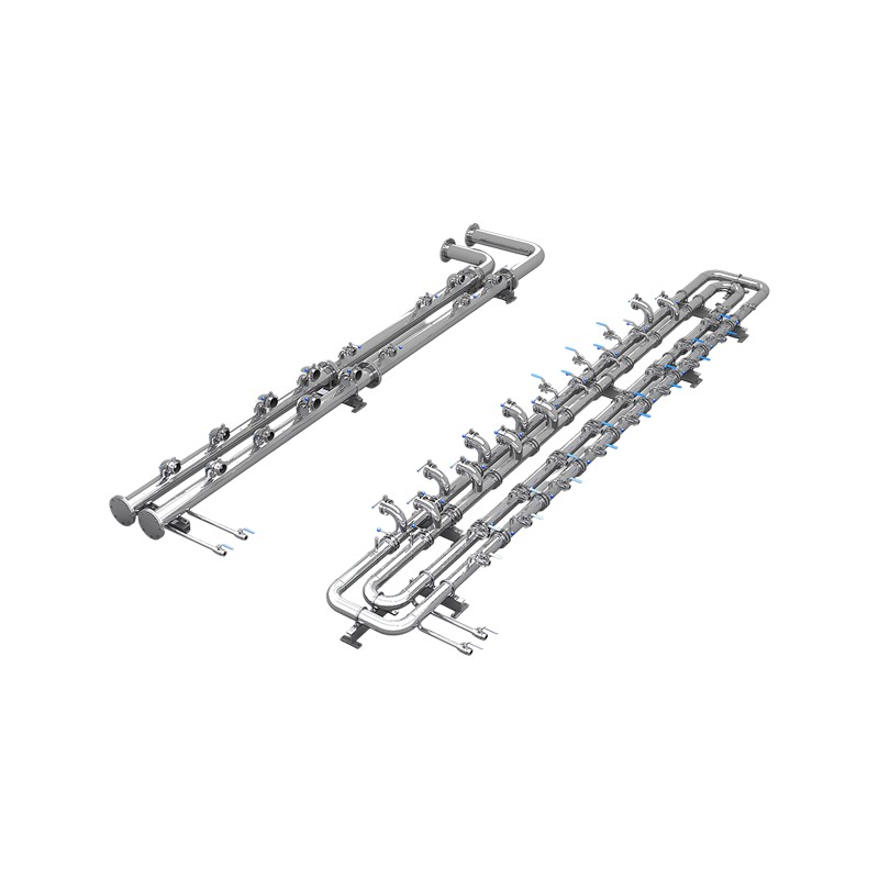
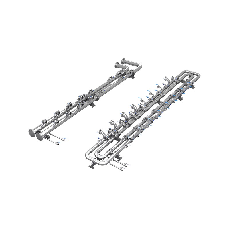
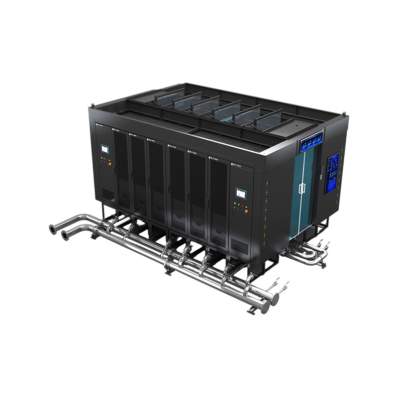
Product OverviewWM-SCL Secondary-Side Prefabricated Piping is a standardized coolant distribution system that connects the CDU to liquid-cooled server cabinets. The piping is prefabricated and quality...
See Details -
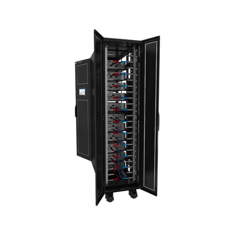
Product OverviewWM-LCR Liquid-Cooled Server Cabinet is a dedicated data center cabinet system that uses liquid as the cooling medium. Through circulating coolant, it efficiently transfers heat generat...
See Details -
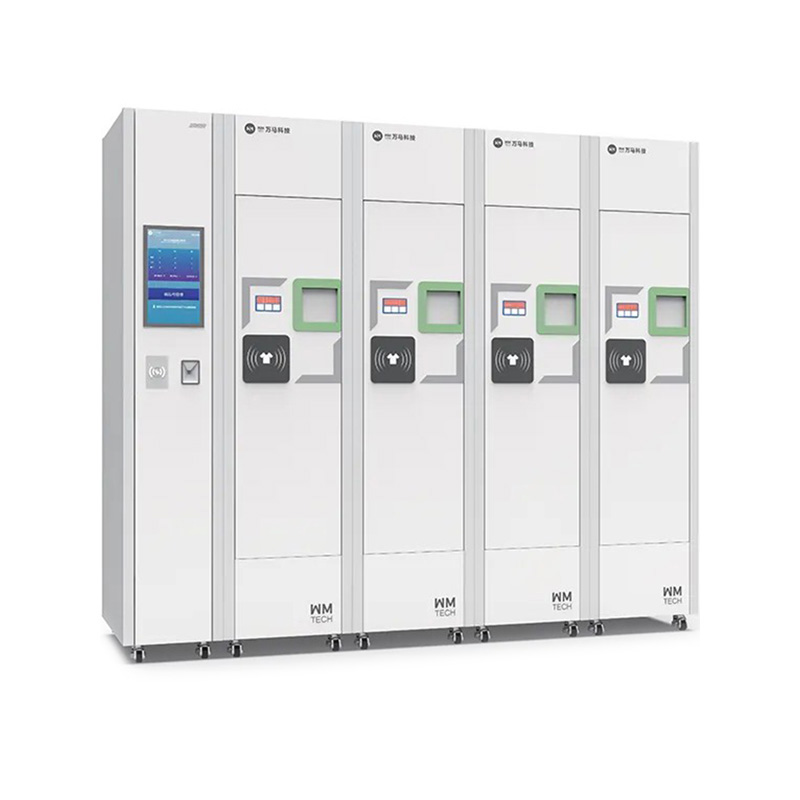
Product Definition:The Chain Intelligent Clothes and Shoes Sending Machine is an advanced management system for hospital operating rooms and clean zones, integrating automatic storage, identity verifi...
See Details
Ready to Get started ? Contact Us Now !

Product.
Contact Details.
-
 +86 13958188250
-
 +86 13958188250
-
 [email protected]
- Wanma Industrial Park Taihu Yuan Town Lin'an District Hangzhou City China.
QR Code

Copyright © Wanma Technology Co., Ltd. All Rights Reserved.
Privacy
Custom Ethernet Optical Network Railway Transit Equipments Suppliers
