

 English
 Français
 Español
 Português
 عربى





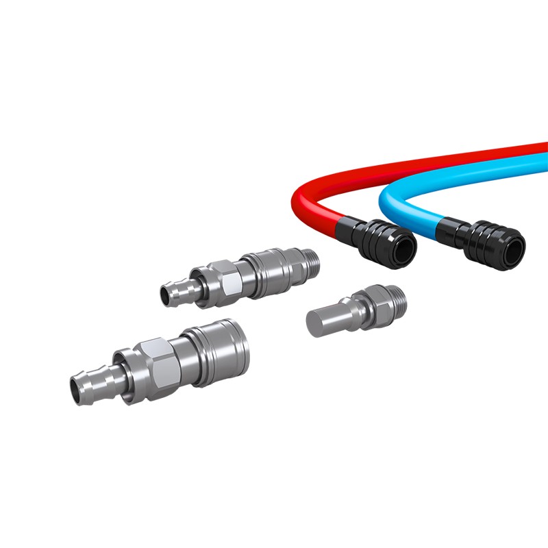
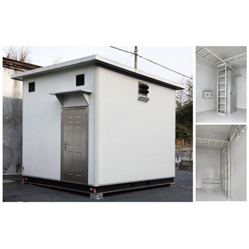
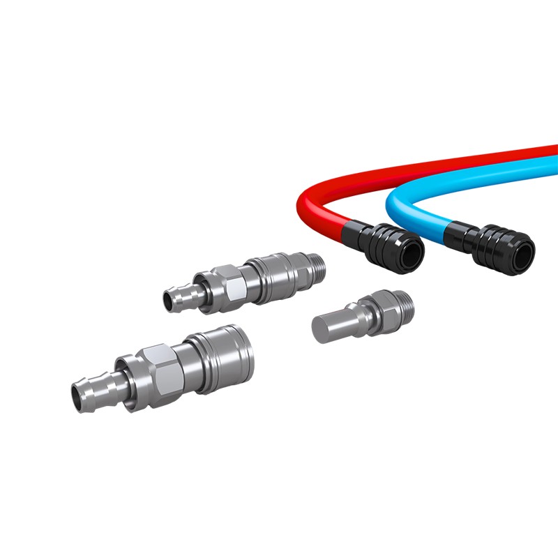
Product OverviewWM-UQD Liquid Cooling Quick Disconnect Coupling is a fluid connection component specifically designed for online maintenance of liquid cooling systems. Both the plug and socket are equ...
See DetailsWhat Causes Self-Sealing Quick Couplers and Hoses to Fail and How to Maintain Them
Content
- 1 Why Self-Sealing Quick Disconnects Are Reliability-Critical Nodes
- 2 Common Failure Modes: Five Root Causes of Quick Coupler and Hose Failure
- 3 Maintenance Tips for Extending Quick Coupler and Hose Life
- 4 How to Select the Right Quick Couplers and Hoses for Your Application
- 5 Frequently Asked Questions
- 5.0.1 Q1: Why does my quick coupler leak after only a few disconnect cycles?
- 5.0.2 Q2: How often should O-rings be replaced?
- 5.0.3 Q3: Can I use compressed air to clean a quick disconnect coupling?
- 5.0.4 Q4: What causes brinelling and how can I prevent it?
- 5.0.5 Q5: Is a dry-break coupling truly drip-free?
- 5.0.6 Q6: How do I choose between 02, 04, 06, and 08 sizes?
- 6 Conclusion
A single drip at a coupling interface can be more expensive than the entire connection. In liquid cooling loops for data centers, power electronics, and medical imaging systems, a microscopic leak path can bridge energized components, corrode traces, or trigger unplanned maintenance windows. The reliability of quick couplers and hoses therefore sits at the center of system uptime.
Most field failures do not originate from a manufacturing defect. They emerge from a mismatch between fluid, material, installation torque, and maintenance practice. This article breaks down five root causes, provides inspection and cleaning procedures, and explains how to match coupler and hose specifications to real operating conditions.
Why Self-Sealing Quick Disconnects Are Reliability-Critical Nodes
A self-sealing quick disconnect coupling performs two functions simultaneously: it locks a fluid line mechanically and seals it hydraulically the moment the two halves separate. In a hot-swap maintenance scenario, that dual action protects both the operator and the electronics downstream.
Three operational realities make these components reliability-critical:
- Thermal cycling: Repeated heating and cooling changes seal compression and can accelerate elastomer fatigue.
- Vibration exposure: Pumps, fans, and nearby machinery transmit vibration into the coupling body and locking mechanism.
- Human interface: Couplings are connected and disconnected by technicians under time pressure, making installation quality variable.
A 2021 industry survey of liquid cooling maintenance records found that roughly 60 percent of reported leaks traced back to seal degradation, contamination, or improper connection practice rather than catastrophic body failure. That distribution shapes the failure modes described below.
Common Failure Modes: Five Root Causes of Quick Coupler and Hose Failure
1. Seal Degradation and Fluid Incompatibility
O-rings and molded seals are the primary barrier in any self-sealing coupling. When the seal material is incompatible with the coolant chemistry, it can swell, harden, crack, or dissolve. Deionized water is aggressive toward many elastomers because it leaches plasticizers and ions. Ethylene glycol and propylene glycol mixtures add their own chemical load.
EPDM (ethylene propylene diene monomer) is widely specified for deionized water and glycol loops because it resists polar fluids and maintains elasticity across a broad temperature range. However, EPDM is not universal. Systems using ester-based fluids, some synthetic hydrocarbons, or aggressive additives may require fluoroelastomer or other specialty seals.
Warning signs appear before visible leakage:
- Seal surface becomes glossy or tacky
- O-ring cross-section no longer returns to original shape after compression
- Color shift or surface crazing
- Black residue on the sealing face
2. Brinelling and Vibration Damage
Brinelling is permanent indentation of the metal surface where locking balls or pins contact the mating half. Under continuous vibration or side load, the balls hammer the shoulder of the male half, creating shallow craters. Once the indentations deepen, the coupling no longer seats at the designed depth, and the seal loses compression.
Stainless steel bodies, particularly 304 and 316L, offer better resistance to brinelling than brass or aluminum because of higher surface hardness and fatigue strength. Material selection alone does not eliminate the risk. Routing practice matters equally.
A short flexible whip hose between a rigid manifold and the quick disconnect acts as a vibration isolator. It absorbs lateral displacement and reduces the impact load on the locking mechanism. Installations that rigidly couple a pump outlet directly to a quick disconnect without a flexible section show noticeably higher brinelling rates.
3. Contamination at the Coupling Interface
The sealing face of a quick disconnect is a precision surface. A particle of metal debris, dust, or dried coolant residue trapped between the mating faces creates a leak path that no amount of torque can close. Contamination also scratches the O-ring and the flat valve seat, turning a reusable coupling into a disposable one.
Sources of contamination include:
- Open ports exposed to shop air during maintenance
- Cutting or grinding debris from nearby fabrication
- Internal hose degradation releasing particles into the fluid stream
- Improper cleaning tools that shed fibers or leave residue
Dust caps are not optional accessories. They are part of the sealing system. A coupling left uncapped for even a few hours in an active mechanical room can accumulate enough particulate to compromise the next connection.
4. Spillage and Dry-Break Misconceptions
The term dry-break is often used loosely. In practice, every quick disconnect traps a small volume of fluid in the dead space between the valve and the sealing face. When the halves separate, that volume is released. The question is how much and under what conditions.
A well-designed flat-face coupling minimizes dead volume. At low pressure and with proper alignment, the spillage per disconnect may be a fraction of a milliliter. At higher pressure, with worn seals, or with side-loaded disconnection, the released volume increases significantly.
Table 1 compares expected spillage behavior across operating conditions.
| Condition | Expected Spillage | Primary Influence |
|---|---|---|
| New coupling, low pressure, aligned | Minimal, sub-milliliter | Dead volume design |
| New coupling, rated pressure, aligned | Small, measurable droplets | Fluid compressibility and valve timing |
| Worn seal, rated pressure, aligned | Increased droplet formation | Seal compression loss |
| Any condition, side-loaded disconnect | Highest spillage risk | Valve misalignment and seal bypass |
The practical takeaway is not that dry-break couplings fail to perform. It is that dry-break performance depends on correct operation and maintained seals. A coupling advertised as dry-break will still drip if the O-ring is swollen or the technician twists the halves apart.
5. Thread and Connection Failures
Threaded connections between the coupler and the hose or manifold introduce a second sealing interface. Over-torque stretches threads, distorts the body, and can crack the hex flats. Under-torque leaves the connection loose, allowing vibration to work the threads apart and creating a leak path at the thread seal.
Common thread specifications in liquid cooling range from G1/8 to G1/2. Each size has a recommended installation torque that balances sealing force against material stress. A torque wrench is not optional for critical connections. Hand-tight plus a quarter turn is a field habit, not a specification.
Cross-threading and mismatched coupling halves are equally damaging. Forcing a non-mating pair together can deform the sealing face before the threads even engage. Visual indexing features and keyed designs reduce this risk, but they do not replace careful installation.
Maintenance Tips for Extending Quick Coupler and Hose Life
Routine Inspection Checklist
Inspection frequency depends on duty cycle. A coupling cycled daily needs monthly inspection. A coupling in continuous service with infrequent disconnection needs quarterly inspection. The following checklist covers the highest-risk items:
- Sealing face: Look for scratches, dents, or embedded particles. A fingernail dragged across the face will catch on damage invisible to the eye.
- O-ring: Check for swelling, flattening, cracking, or color change. Compare a used O-ring to a new one of the same size.
- Locking mechanism: Verify that balls or pins move freely and that the sleeve returns to the locked position without sticking.
- Hose exterior: Inspect for abrasion, cuts, blistering, or stiffness that indicates aged elastomer.
- Threads: Check for galling, cross-threading, or corrosion that would prevent proper torque.
Proper Cleaning and Storage Procedures
Compressed air is a common cleaning choice and a common mistake. Shop air contains moisture and oil aerosol that deposit on the sealing face. The air stream can also drive particles deeper into the valve body where they migrate to the seal during the next connection.
Use a lint-free cloth dampened with clean deionized water or a compatible cleaning solvent. Wipe the sealing face and the exterior of the coupling. Allow to dry fully before capping or connecting. Store disconnected couplings with protective caps installed. Store hoses coiled to the manufacturer's minimum bend radius, not folded or hung by the coupling.
Hot-Swap and Connect-Under-Pressure Best Practices
Connect-under-pressure capability is a design feature, not a license for careless operation. The following practices reduce seal stress and spillage:
- Align the two halves before applying axial force. Off-axis insertion loads the seal unevenly.
- Push straight in until the locking mechanism engages audibly or tactilely. Do not twist unless the coupling is designed for twist-lock operation.
- Disconnect with the same axial alignment. Pulling at an angle can score the sealing face.
- Respect the maximum working pressure rating. A coupling rated for 1.6 MPa should not be connected or disconnected while the system is at or above that limit.
- After connection, perform a visual check for weeping at the interface before restoring full system pressure.
How to Select the Right Quick Couplers and Hoses for Your Application
Matching Materials to Cooling Fluids
Material selection begins with the fluid. Table 2 summarizes common coolant types and the seal and body materials that perform reliably.
| Coolant Type | Recommended Seal | Body Material | Notes |
|---|---|---|---|
| Deionized water | EPDM | 304 or 316L stainless steel | Avoid brass; ion leaching risk |
| Ethylene glycol mixture | EPDM | 304 or 316L stainless steel | Confirm additive compatibility |
| Propylene glycol mixture | EPDM | 304 or 316L stainless steel | Similar to ethylene glycol |
| Synthetic hydrocarbon | Fluoroelastomer | 316L stainless steel | Verify with fluid supplier |
| Ester-based fluid | Fluoroelastomer | 316L stainless steel | EPDM may swell |
Sizing and Flow Considerations
Quick couplers and hoses are available in nominal sizes such as 02, 04, 06, and 08. The number generally corresponds to the internal flow diameter in sixteenths of an inch or a related metric convention. Choosing a size that is too small creates excessive pressure drop and forces the pump to work harder. Choosing a size that is too large wastes space, adds fluid volume, and can reduce flow velocity below the level needed for proper heat transfer in some loop designs.
Pressure drop across a coupling is not linear with flow. It rises with the square of flow rate. A coupling that performs acceptably at half flow may become a significant restriction at full flow. Review the flow coefficient or pressure drop curve for the specific coupling size and compare it to the system curve.
Why Specification Discipline Matters More Than Brand
Two couplings with identical thread sizes and similar appearance can have different seal materials, different locking mechanisms, and different pressure ratings. Selecting by appearance or by catalog number alone invites mismatch. The specification sheet is the controlling document. Verify seal material, body alloy, pressure rating, temperature range, and thread standard against the actual operating conditions before installation.
For custom system integration, OEM and ODM support allows thread, size, and packaging modifications to match existing manifolds and maintenance procedures. This reduces adapter count and eliminates an entire class of thread mismatch failures. A supplier with in-house machining and assembly can also provide batch traceability, which shortens root cause analysis when a field issue does occur.
Frequently Asked Questions
Q1: Why does my quick coupler leak after only a few disconnect cycles?
Early-life leakage usually points to seal damage during installation or contamination at the interface. Inspect the O-ring for cuts or swelling and check the sealing face for embedded particles. If the coupling was connected under pressure or with side load, the seal may have been deformed before it seated. Replace the seal and reconnect with axial alignment at zero or low pressure.
Q2: How often should O-rings be replaced?
Replacement interval depends on fluid chemistry, temperature cycling, and connection frequency. In a clean deionized water loop with monthly disconnects, annual seal replacement is a reasonable baseline. In glycol loops with high thermal cycling or in contaminated environments, replace seals every six months or at the first sign of swelling, hardening, or color change.
Q3: Can I use compressed air to clean a quick disconnect coupling?
Compressed air is not recommended. Shop air carries moisture, oil aerosol, and particulate that can deposit on the sealing face or migrate into the valve body. Use a lint-free cloth dampened with clean deionized water or a compatible solvent, then allow the coupling to dry fully before capping or connecting.
Q4: What causes brinelling and how can I prevent it?
Brinelling is caused by vibration or side load that makes the locking balls hammer the male half, creating indentations. Prevent it by using a flexible whip hose between rigid equipment and the coupling, by supporting the hose to avoid tension at the connection, and by selecting stainless steel bodies with good surface hardness. Regular inspection of the locking mechanism will reveal early brinelling before leakage begins.
Q5: Is a dry-break coupling truly drip-free?
No coupling is absolutely drip-free under all conditions. A well-designed flat-face coupling minimizes dead volume and spillage, but a small amount of fluid is released on each disconnect. Spillage increases with pressure, seal wear, and misalignment. Treat dry-break as a performance target that depends on correct operation and maintained seals, not as an absolute guarantee.
Q6: How do I choose between 02, 04, 06, and 08 sizes?
Size selection balances flow rate, pressure drop, and space. Smaller sizes save space but create higher pressure drop and pump load. Larger sizes reduce pressure drop but add fluid volume and cost. Review the pressure drop curve for the candidate size at the system's design flow rate, and confirm that the resulting drop is acceptable for the pump and heat exchanger performance.
Conclusion
Reliable liquid cooling connections are not the result of a single good component. They are the result of matching seal material to fluid, selecting the correct size and pressure rating, installing with controlled torque and alignment, and maintaining the coupling throughout its service life. The five failure modes described here, seal degradation, brinelling, contamination, spillage misconceptions, and thread damage, account for the majority of field issues. Each has a practical countermeasure that costs far less than the downtime it prevents.
Review the specification table for the couplings and hoses in your system. Confirm seal material, body alloy, thread standard, and pressure rating against actual operating conditions. Then build an inspection interval that reflects how often the coupling is cycled and how aggressive the fluid environment is. Those two steps, verification and inspection, eliminate most unexpected leaks before they start.
PREV:What Makes a Sorting and Packaging Station the Critical Control Point in Medical Fabric Management?
NEXT:Why Prefabricated Piping for Liquid Cooling Secondary Side Is Reshaping Data Center Deployment
NEXT:Why Prefabricated Piping for Liquid Cooling Secondary Side Is Reshaping Data Center Deployment
Interested in cooperation or have questions?
Related products
-
-
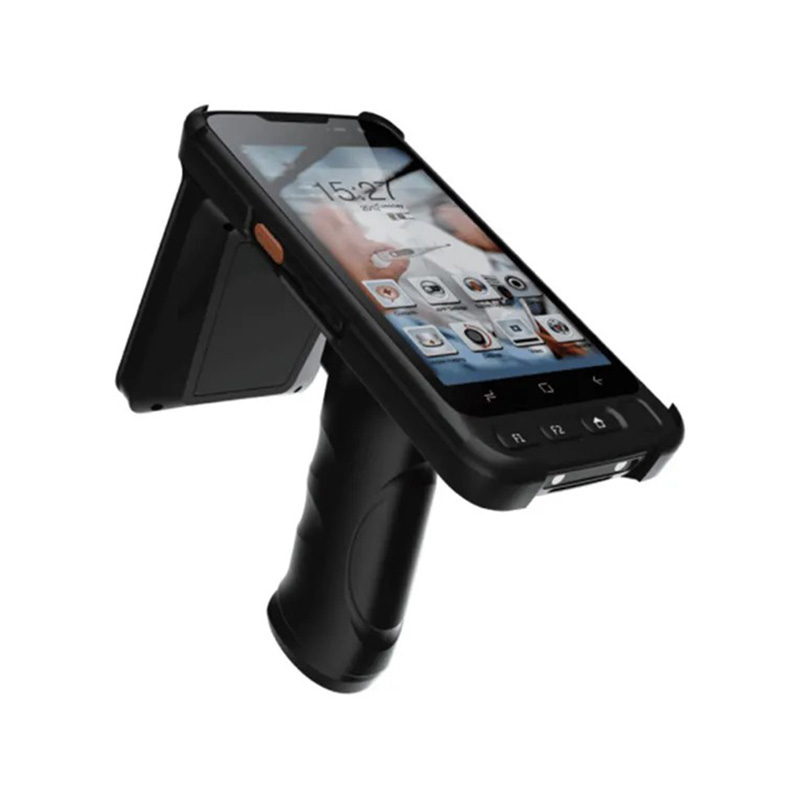
Product Definition:The RFID Handheld Inventory Device is the core mobile terminal of the Intelligent Medical Fabric Management System, designed for high-efficiency inventory and handover of linens in ...
See Details -

Application:It is suitable for the connection of Bow-type cables and is mainly used in optical fiber termination box, optical fiber distribution box, Household intelligent box, optical fiber socket-bo...
See Details -

Application:The patch cord, pigtail and adapter are optical devices mainly used in OMDF, ODF, OCC and other optical distribution equipments. Features:•It adopts high-precision ceramic ferrule featurin...
See Details
Ready to Get started ? Contact Us Now !

Product.
Contact Details.
-
 +86 13958188250
-
 +86 13958188250
-
 [email protected]
-
 AUDIT Email:[email protected]
- Wanma Industrial Park Taihu Yuan Town Lin'an District Hangzhou City China.
QR Code

Copyright © Wanma Technology Co., Ltd. All Rights Reserved.
Privacy
Custom Ethernet Optical Network Railway Transit Equipments Suppliers
